
Gantry Crane Cart Attitude Control Method and Device

A gantry crane and attitude control technology, which is applied in the direction of traveling mechanism, transportation and packaging, load hanging components, etc., can solve the problems of insufficient accuracy of deviation correction, no better problem, etc., and achieve more accurate and efficient deviation correction effect

Active Publication Date: 2020-12-25
SANY MARINE HEAVY IND
View PDF7 Cites 0 Cited by
  • Summary
  • Abstract
  • Description
  • Claims
  • Application Information

AI Technical Summary

Problems solved by technology

At present, the existing automatic deviation correction and positioning schemes include: GPS differential amplification correction and positioning, ground marking and image recognition deviation correction and positioning, and photoelectric distance measurement and deviation correction. The lack of precision has not yet proposed a better solution

Method used


Image

  • Gantry Crane Cart Attitude Control Method and Device
  • Gantry Crane Cart Attitude Control Method and Device
  • Gantry Crane Cart Attitude Control Method and Device

Examples


Embodiment 1

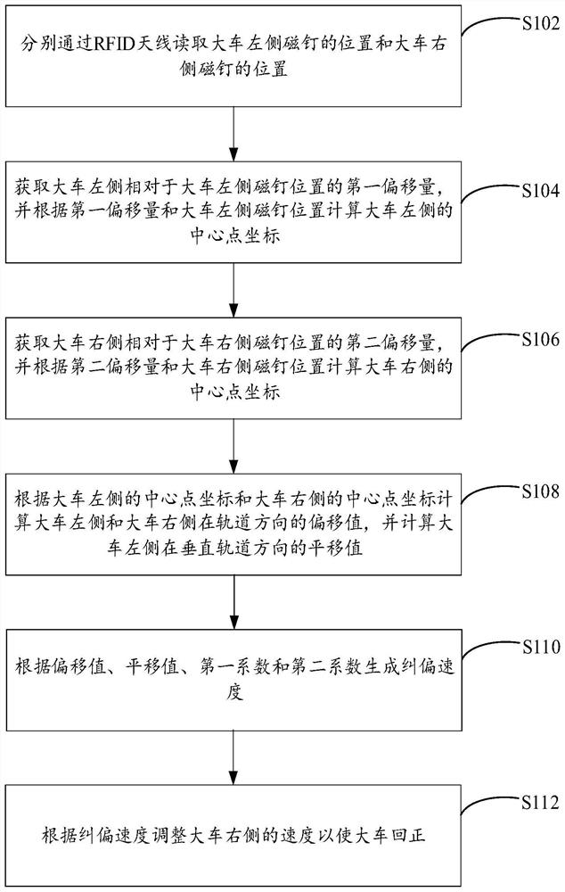
[0040] Embodiment 1 of the present invention provides a method for controlling the attitude of a gantry crane cart, see figure 1 The flow chart of the attitude control method for the gantry crane cart shown in the figure, the method includes the following steps:

[0041] Step S102, read the positions of the magnetic nails on the left side of the cart and the magnetic nails on the right side of the cart through the RFID antenna respectively; The center line and the center line of the track on the right side of the cart; the center line of the track on the left side of the cart is parallel to the center line of the track on the right side of the cart.

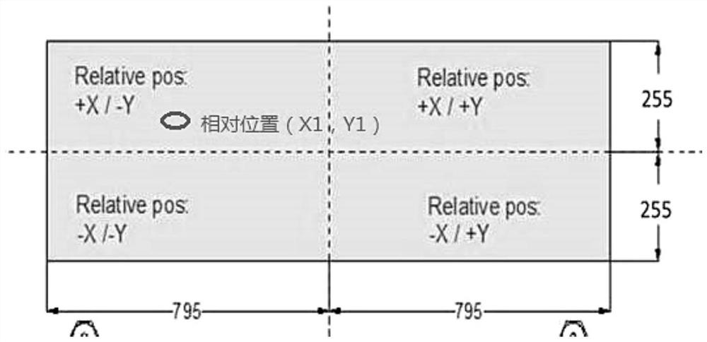
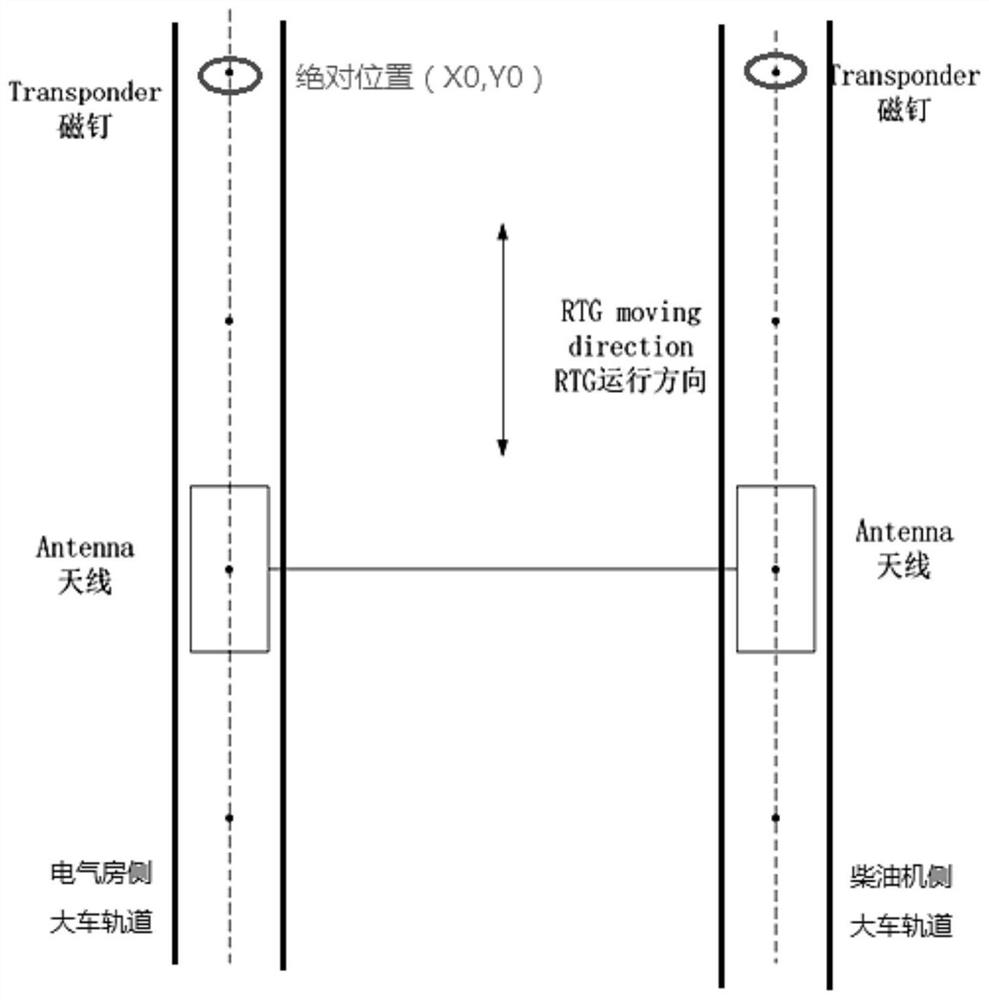
[0042] The Rubber Tire Gantry (RTG) includes the electrical room side and the power room side. Right. Absolute position information is stored in the magnetic nails, which are respectively arranged at intervals on the centerline of the track on the left side of the cart and on the centerline of the track on the right side of the...

Embodiment 2

[0070] Embodiment 2 of the present invention provides a gantry crane cart attitude control device, see Figure 9 The schematic block diagram of the structure of the attitude control device of the gantry crane shown in the figure, the device includes:

[0071] The position module 91 is used to read the position of the magnetic nails on the left side of the cart and the magnetic nails on the right side of the cart through the RFID antenna respectively; The center line of the left track and the center line of the right track of the cart; the center line of the left track of the cart is parallel to the center line of the right track of the cart; the left coordinate calculation module 92 is used to obtain the left side of the cart relative to the left side of the cart The first offset of the side magnetic nail position, and calculate the center point coordinates on the left side of the cart according to the first offset and the magnetic nail position on the left side of the cart; t...

Embodiment 3

[0078] Embodiment 3 of the present invention provides a method for controlling the attitude of a gantry crane cart.

[0079] The attitude of the RTG during the operation of the cart can be determined by the following two parameters, the longitudinal deviation ΔY of the cart along the direction of the track and the lateral deviation ΔX perpendicular to the direction of the track. Among them, longitudinal deviation △Y: check the overall deflection angle of the cart relative to the track center. Lateral deviation △X: Check the overall translation distance of the cart relative to the center of the track.

[0080] The deviation correction method samples the speed difference to control, and keeps the speed reference on the electrical room side unchanged. When △Y is a negative value, reduce the speed reference on the diesel engine side, and when △Y is a positive value, increase the speed reference on the diesel engine side . The speed difference is jointly determined by △Y and △X. ...


PUM


Abstract

The invention provides an attitude control method and an attitude control device for a gantry crane cart, and relates to the technical field of intelligent control. The attitude control method includes reading the position of a magnetic nail on the left side of the cart and the position of a magnetic nail on the right side of the cart through an RFID antenna respectively; calculating the coordinates of the center point of the left side of the cart according to the first offset and the position of the magnetic nail on the left side of the cart; calculating the coordinates of the center point ofthe right side of the cart according to the second offset and the position of the magnetic nail on the right side of the cart; calculating the offset values of the left side and the right side of thecart in the track direction according to the coordinates of the center point on the left side of the cart and the coordinates of the center point on the right side of the cart, and calculating the translation value of the left side of the cart in the direction perpendicular to the track; generating a correction speed according to the offset values, the transition value, a first coefficient and asecond coefficient; adjusting the speed of the right side of the cart according to the correction speed to reset the cart. The attitude control method and the attitude control device have the advantages that the two sides of the cart are accurately positioned through the RFID antenna, the correction speed is calculated, and accurate and efficient correction of the position of the cart is realized.

Description

technical field [0001] The invention relates to the technical field of intelligent control, in particular to a method and device for controlling the attitude of a gantry crane cart. Background technique [0002] At present, with the continuous development of the machinery manufacturing industry, the application occasions of gantry cranes are increasing, and the requirements for safety are also increasing. RTG (Rubber Tire Gantry, rubber tire gantry crane) can be used for container transfer in the yard. Due to the use of tire-type cart mechanism, it can be very flexible in transition, which greatly improves the efficiency of RTG. However, since there is no fixed track, when the weight on both sides of the cart is unbalanced, or the tire pressure is unbalanced, or the road surface of the road is uneven, it is very easy to cause the cart to deviate from the track during operation, affect the working efficiency, and even cause accidents. Due to the above reasons, the automatic ...

Claims


Application Information

Patent Timeline
Patent Type & Authority Patents(China)
IPC IPC(8): B66C13/40B66C13/46B66C13/16B66C9/16
CPCB66C9/16B66C13/16B66C13/40B66C13/46
Inventor 唐修俊马铭余磊
Owner SANY MARINE HEAVY IND
Learn More