Heat pump drying system

A technology of heat pump drying and drying chamber, which is applied in the direction of drying solid materials, drying gas arrangement, local agitation dryer, etc. It can solve the problems that the evaporator cannot meet the process requirements of large flow drying medium and the heat transfer performance of the condenser is difficult to adjust, etc. Achieve the effect of conveniently controlling heat balance and changing heat dissipation performance

Active Publication Date: 2019-03-01
卡塞尔机械(浙江)有限公司
View PDF7 Cites 0 Cited by
  • Summary
  • Abstract
  • Description
  • Claims
  • Application Information

AI Technical Summary

Problems solved by technology

However, the heat transfer performance of the condenser in the existing heat pump drying system is not easy to adjust, and a single evaporator and condenser connected in series cannot meet the technological requirements of large flow drying media

Method used


Image

  • Heat pump drying system

Examples


Embodiment Construction

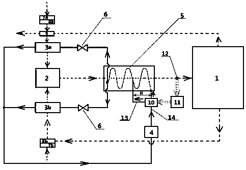
[0023] see figure 1 The heat pump drying system provided in this embodiment includes a drying chamber 1, a fan 2, a first evaporator 3a, a second evaporator 3b, a compressor 4, a condenser 5, a throttle valve 6, a first fresh air valve 7a, a second Two fresh air valves 7b, a first air filter 8a, a second air filter 8b, a heat exchanger 9, a three-way valve 10, a controller 11, and a temperature and humidity sensor 12.

[0024] The first evaporator 3a and the second evaporator 3b are arranged side by side in parallel, and are connected in series with the coiled tube of the condenser 5. Between the first evaporator 3a and the condenser 5 and the second evaporator 3b and the The connecting pipes of the condenser 5 are respectively provided with the throttle valve 6, the fan 2 is installed in the middle of the first evaporator 3a and the second evaporator 3b, and the first evaporator 3a and the second evaporator 3b The air outlet of the second evaporator 3b communicates with the ...


PUM


Abstract

The invention provides a heat pump drying system. The heat pump drying system comprises a drying chamber, a fan, a first evaporator, a second evaporator, a compressor, a condenser, a throttle valve, afirst outside air damper, a second outside air damper, a first air filter, a second air filter, a heat exchanger, a three-way valve, a controller and a temperature and humidity sensor. The first evaporator and the second evaporator arranged in parallel, and the first evaporator and a coiled pipe of the condenser are connected in series; the fan is arranged between the first evaporator and the second evaporator; and an air outlet of the fan directly faces an air inlet of the condenser and communicates with the air inlet of the condenser, so that large-flow dry air is supplied. A bypass pipeline is arranged on a connecting pipeline between the compressor and the condenser, the bypass pipeline enters the condenser at a predetermined distance H from an inlet point of the coiled pipe of the condenser and communicates with the coiled pipe, and a three-way valve is arranged at the intersection between the bypass pipeline and the connecting pipeline. By driving the three-way valve, the heat dissipation performance of the condenser can be changed, and the heat balance can be conveniently controlled.

Description

technical field [0001] The invention belongs to the field of drying, and in particular relates to a heat pump drying system. Background technique [0002] The heat pump can effectively recover the latent and sensible heat in the humid air, significantly improving energy utilization. The drying medium flow rate, temperature and humidity required by different products to be dried are not the same. When the product to be dried at one time in the drying room is large, it is usually necessary to increase the supply of drying medium per unit time, otherwise it will be necessary to extend the drying time. The unit drying time will reduce the production efficiency. Moreover, the product and quantity to be dried may be different each time, so the supply of drying medium and temperature and humidity must be adjusted accordingly each time. However, the heat transfer performance of the condenser in the existing heat pump drying system is not easy to adjust, and a single evaporator con...

Claims


Application Information

Patent Timeline
IPC IPC(8): F26B9/06F26B21/00F26B21/08F26B25/00
CPCF26B9/06F26B21/002F26B21/003F26B21/004F26B21/08F26B25/00F26B25/007
Inventor 黄有海周兴旺
Owner 卡塞尔机械(浙江)有限公司
Why Eureka
Try Eureka