Sensor and method for preparing same
A sensor, piezoresistive sensor technology, applied in the field of detection, can solve the problems of complex positive pressure signal processing algorithm, difficult to install on the surface of prosthesis, low sensitivity and resolution of sliding signal, etc., to achieve the effect of improving accuracy
- Summary
- Abstract
- Description
- Claims
- Application Information
AI Technical Summary
Problems solved by technology
Method used
Image
Examples
Embodiment 1
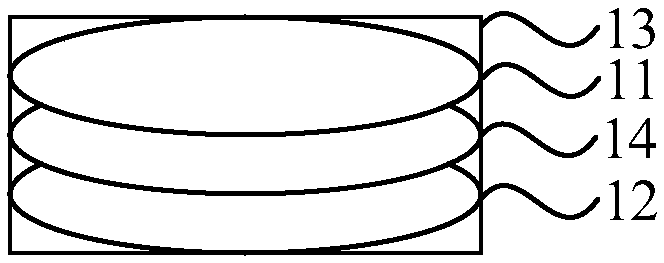
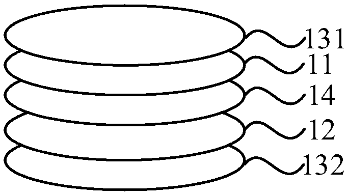
[0033] figure 1 This is a schematic structural diagram of a sensor provided in the first embodiment of the present invention. This embodiment can be applied to the situation of detecting tactile signals, such as figure 1 As shown, the sensor may specifically include: a piezoelectric electret sensor 11, a piezoresistive sensor 12, a protective member 13, and a buffer layer 14. The structure and function of the sensor are described below.
[0034] The buffer layer 14 is arranged between the piezoelectric electret sensor 11 and the piezoresistive sensor 12, and the piezoelectric electret sensor 11 and the piezoresistive sensor 12 are embedded in the protective member 13.
[0035] In the embodiment of the present invention, a tactile sensor is added to the prosthesis to realize real-time feedback of the motion state between the prosthesis and the object, and as a real-time control signal of the prosthetic control system to realize the closed-loop control of the prosthetic grip with a hig...
Embodiment 2
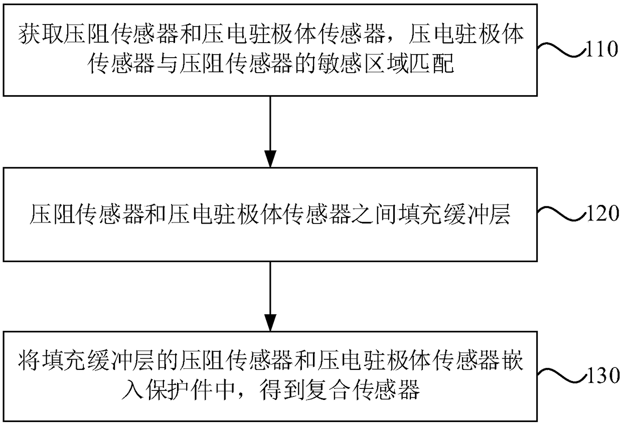
[0054] image 3 This is a flowchart of a method for manufacturing a sensor provided in the second embodiment of the present invention. This embodiment can be applied to the case of detecting tactile signals. Such as image 3 As shown, the method specifically includes the following steps:
[0055] Step 110: Obtain a piezoelectric electret sensor and a piezoresistive sensor, and the sensitive areas of the piezoelectric electret sensor and the piezoresistive sensor are matched.
[0056] Step 120: Fill a buffer layer between the piezoelectric electret sensor and the piezoresistive sensor.
[0057] Step 130: Embed the piezoelectric electret sensor and the piezoresistive sensor filled with the buffer layer in the protective member to obtain a composite sensor.
[0058] In the embodiment of the present invention, a piezoelectric electret sensor and a piezoresistive sensor are acquired, where the piezoresistive sensor needs to meet preset conditions, and the preset conditions may specifically...
Embodiment 3
[0069] Figure 4 This is a flowchart of a method for manufacturing a sensor provided in the third embodiment of the present invention. This embodiment can be applied to the case of detecting tactile signals. Such as Figure 4 As shown, the method specifically includes the following steps:
[0070] Step 210: Select a piezoelectric electret and a piezoresistive sensor that meets preset conditions. The preset conditions include size, size, and range.
[0071] Step 220: Shear the piezoelectric electret sensor to match the sensitive area of the piezoelectric electret sensor and the piezoresistive sensor.
[0072] Step 230: Fill a buffer layer between the piezoelectric electret sensor and the piezoresistive sensor.
[0073] Step 240: Stick the first protective layer on the outer surface of the piezoelectric electret sensor, and stick the second protective layer on the outer surface of the piezoresistive sensor.
[0074] Step 250, encapsulating the piezoelectric electret sensor, the piezore...
PUM
 Abstract
Description
Claims
Application Information
 - R&D
- Intellectual Property
- Life Sciences
- Materials
- Tech Scout
- Unparalleled Data Quality
- Higher Quality Content
- 60% Fewer Hallucinations
Browse by: Latest US Patents, China's latest patents, Technical Efficacy Thesaurus, Application Domain, Technology Topic, Popular Technical Reports.
© 2025 PatSnap. All rights reserved.Legal|Privacy policy|Modern Slavery Act Transparency Statement|Sitemap|About US| Contact US: help@patsnap.com


