T/R module automatic test system structure
A technology of automated testing and system structure, applied in radio wave measurement systems, instruments, etc., can solve problems such as low efficiency, poor reliability, and large workload of T/R component testing
- Summary
- Abstract
- Description
- Claims
- Application Information
AI Technical Summary
Problems solved by technology
Method used
Image

Examples
Embodiment Construction
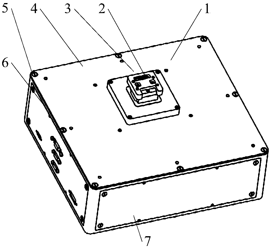
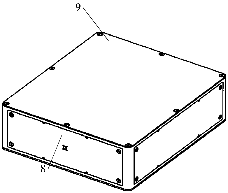
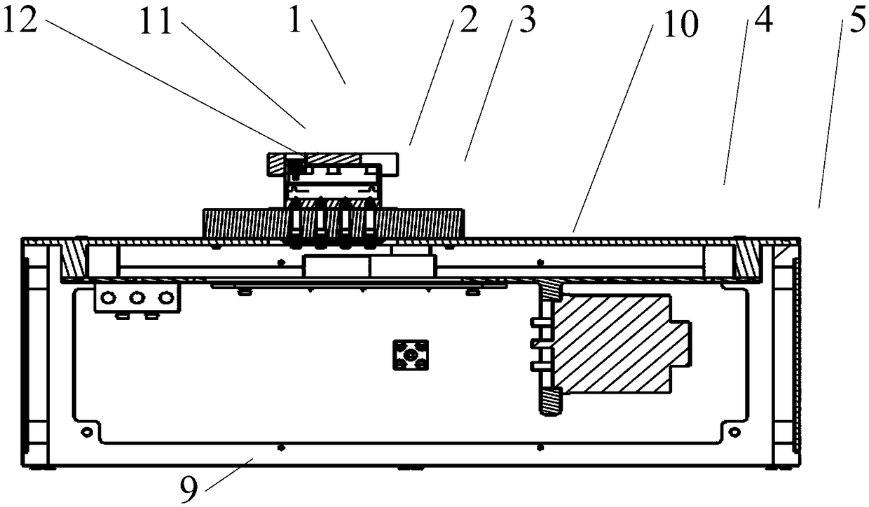
[0028] With reference to the drawings in the specification, a T / R component automated test system structure includes pressure plate 1, thermal pad 2, cold plate 3, upper cover 4, frame 5, A panel 6, side cover 7 (2 pieces), and B panel 8, bottom plate 9, device mounting board 10.
[0029] Such as Figure 1 ~ Figure 3 As shown, during assembly, the thermal pad 2 is attached to the upper surface of the cold plate 3, and then the T / R assembly 11 is installed on the upper surface of the thermal pad 2, and the positioning boss 14 of the cold plate 3 is used to achieve positioning, and then the pressure plate 1 Install it on the T / R assembly 11. Fix the pressure plate 1 on the positioning boss 14 of the cold plate 3 with screws. The tightening torque is about 30cN.m. At this time, the thickness of the thermal pad is compressed from 0.38mm to 0.35mm. Then fix the above components on the upper cover 4. Insert the KK connector 12 from the lower surface of the cold plate 3 through the t...
PUM
| Property | Measurement | Unit |
|---|---|---|
| Thickness | aaaaa | aaaaa |
| Thickness | aaaaa | aaaaa |
Abstract
Description
Claims
Application Information