Wet cleaning equipment

A technology of wet cleaning and equipment, which is applied in the direction of electrical components, semiconductor/solid-state device manufacturing, circuits, etc., can solve problems such as high defect density, achieve the effects of reducing defect density, improving product yield, and slowing down the gas flow rate

Active Publication Date: 2019-03-01
NINGBO SEMICON INT CORP
View PDF11 Cites 1 Cited by
  • Summary
  • Abstract
  • Description
  • Claims
  • Application Information

AI Technical Summary

Problems solved by technology

[0008] The purpose of the present invention is to provide a wet cleaning equipment to overcome the influence of the cleaning liquid on the edge of the wafer, and fundamentally solve the problem of high defect density caused by the contamination solution on the edge of the wafer

Method used


Image

  • Wet cleaning equipment
  • Wet cleaning equipment
  • Wet cleaning equipment

Examples


Embodiment 1

[0091] This embodiment provides a kind of wet cleaning equipment, comprising:

[0092] Rotary table, the surface of the rotary table is provided with an air outlet centered on the central axis of the rotary table, and the rotary table can rotate around the central axis of the rotary table; six pins, the six pins are centered on the central axis of the rotary The upper surface of the table is equidistant from the circumference, and the circular air outlet of the rotary table is set on the inner side of the pins. Multiple pins are used to support the wafer on the rotary table and prevent the wafer from shaking horizontally due to the influence of the air flow; Device components near the wafer edge have increased airflow channels.

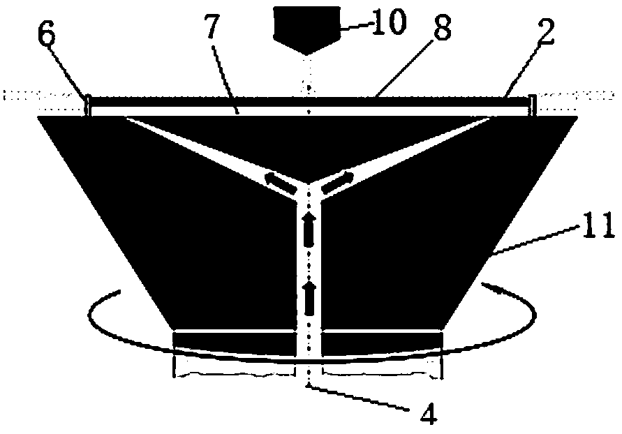
[0093] The interior of the turntable is provided with a gas delivery pipeline connected to the gas outlet. The gas outlet is an annular gas outlet with the center of the turntable as the center. The gas is ejected through the gas outlet to form a gas ...

Embodiment 2

[0097] Figure 8a A schematic diagram of a vertical cross-sectional structure of a rotary table according to an embodiment of the present invention, Figure 8b Another structural schematic diagram of a rotary table according to an embodiment of the present invention, Figure 9 A schematic diagram of the gas flow of a rotary table according to an embodiment of the present invention.

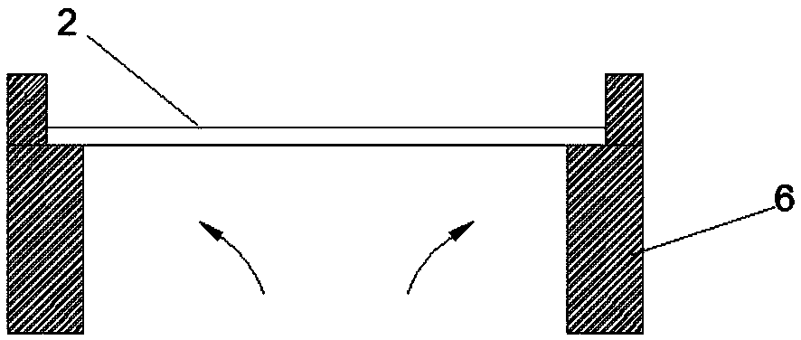
[0098] The embodiment provides a rotary table for wet cleaning equipment, the surface of the rotary table is provided with an annular air outlet 1 centered on the central axis of the rotary table, the rotary table can rotate around the central axis of the rotary table, and the interior of the rotary table is provided with The gas delivery pipeline 4 connected to the annular gas outlet 1 , the increased gas flow channel includes a recess 3 arranged on the turntable, and the recess 3 is close to the edge of the wafer 2 .

[0099] like Figure 8a As shown, when the depression 3 is an annular groov...

Embodiment 3

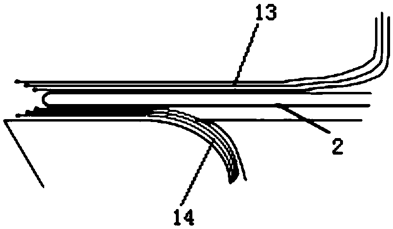
[0103] Figure 4a A schematic diagram of the pin structure of a single through hole according to an embodiment of the present invention, Figure 4b A cross-sectional view of a pin of a single through hole according to an embodiment of the present invention, Figure 5a A schematic diagram of a pin structure of a double through hole according to an embodiment of the present invention, Figure 5b According to an embodiment of the present invention, a cross-sectional view of a pin of a double through hole, Figure 6a A schematic diagram of the pin structure of the frustoconical through hole according to an embodiment of the present invention, Figure 6b A cross-sectional view of pins of a frustum-shaped through hole according to an embodiment of the present invention, Figure 7a A schematic diagram of the gas flow before the gas acts on the wafer according to an embodiment of the present invention, Figure 7b A schematic diagram of gas flow after gas is applied to a wafer acco...


PUM


Abstract

Disclosed is wet cleaning equipment. The wet cleaning equipment comprises a rotating table and a plurality of pins, wherein an air outlet is formed in the surface of the rotating table; the pluralityof pins are arranged, by taking the center axis of the rotating table as a circle center, on the upper surface of the rotating table along the circumference; the air outlet of the rotating table is arranged in the inner sides of the pins; an increased airflow channel is formed in a device component close to the edge of a wafer; and when airflow passes through the increased airflow channel, the flow speed of the air is lowered, and meanwhile, the reverse action of the airflow after the air flow encounters the pins is dredged, so that pollution of a solution flowing from the position of the pinsto the edge of the wafer is reduced, the defect density of the wafer edge is reduced, and the product yield is improved.

Description

technical field [0001] The present invention relates to the technical field of semiconductors, and more specifically, to a wet cleaning device. Background technique [0002] In the integrated circuit manufacturing process, chemicals are often used to clean the wafer and remove some unwanted substances attached to the surface or back of the wafer through chemical reactions. [0003] When the backside of the wafer needs to be chemically cleaned, the chemicals are delivered to the backside of the wafer by turning the wafer upside down. The suction cup of the cleaning equipment usually has several pins, which are used to fix the wafer. After cleaning, some chemicals flow down from the back of the wafer along the pins, and the substances and particles dissolved in the chemicals will be transferred to the edge of the wafer in contact with it, resulting in an increase in the defect density on the front of the wafer, which will eventually affect the quality of the product. yield. ...

Claims


Application Information

Patent Timeline
Patent Type & Authority Applications(China)
IPC IPC(8): H01L21/687H01L21/67
CPCH01L21/67051H01L21/68735
Inventor 陈达
Owner NINGBO SEMICON INT CORP
Why Eureka
Try Eureka