
Broadband antenna for through-wall radar imaging

A broadband antenna and through-the-wall radar technology, applied to antennas, resonant antennas, antenna grounding devices, etc., can solve the problems of low operating frequency band and large antenna size, and achieve the effect of improving gain performance, increasing effective length, and reducing resonance frequency

Pending Publication Date: 2019-03-01
HUNAN NOVASKY ELECTRONICS TECH
View PDF0 Cites 2 Cited by
  • Summary
  • Abstract
  • Description
  • Claims
  • Application Information

AI Technical Summary

Problems solved by technology

Compared with the conventional radar, according to the characteristics of the through-wall radar itself, the use scene and other characteristics, the antenna in the through-wall radar needs to have the characteristics of low working frequency band, wide working bandwidth, high gain, and light weight. In the frequency band, microstrip antennas usually cannot achieve broadband, high gain, and miniaturization at the same time. To achieve broadband and high gain, the corresponding antenna size is relatively large. In order to achieve miniaturized antennas, the corresponding antenna bandwidth and gain often cannot meet the requirements. , using the above-mentioned microstrip antenna in the through-wall radar, it is impossible to take into account the requirements of bandwidth, gain and miniaturization at the same time, so it is urgent to provide a broadband antenna for through-wall radar imaging, so that the broadband and miniaturization can be realized as much as possible , to meet the high gain requirements of through-wall radar imaging

Method used


Image

  • Broadband antenna for through-wall radar imaging
  • Broadband antenna for through-wall radar imaging
  • Broadband antenna for through-wall radar imaging

Examples


Embodiment Construction

[0024] The present invention will be further described below in conjunction with the accompanying drawings and specific preferred embodiments, but the protection scope of the present invention is not limited thereby.

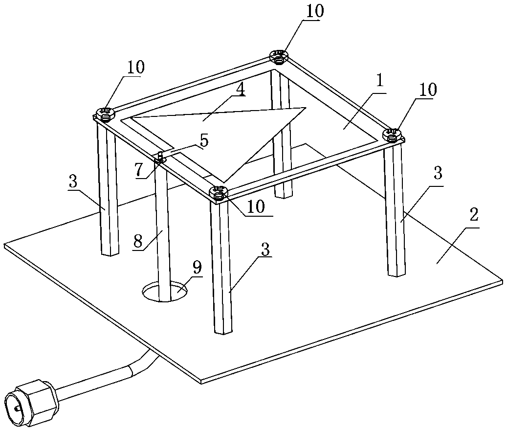
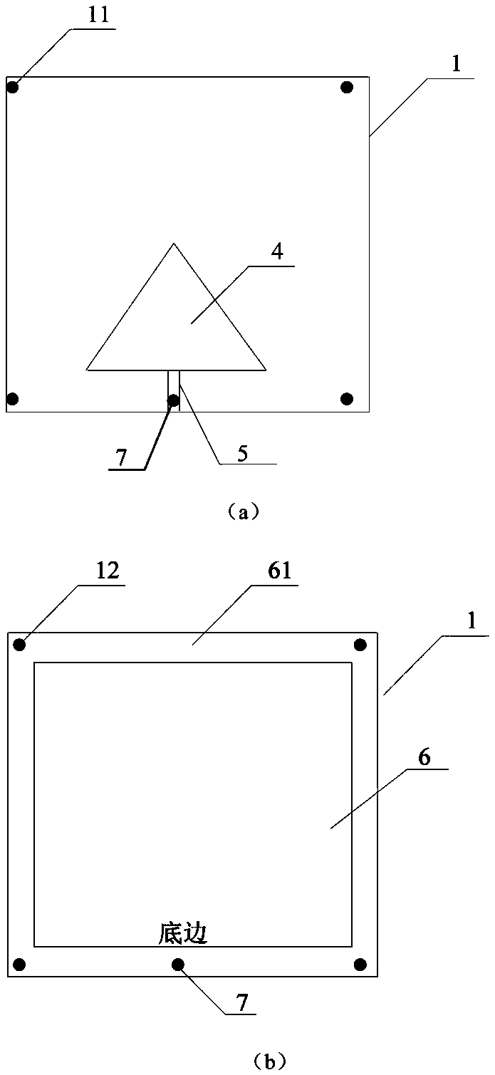
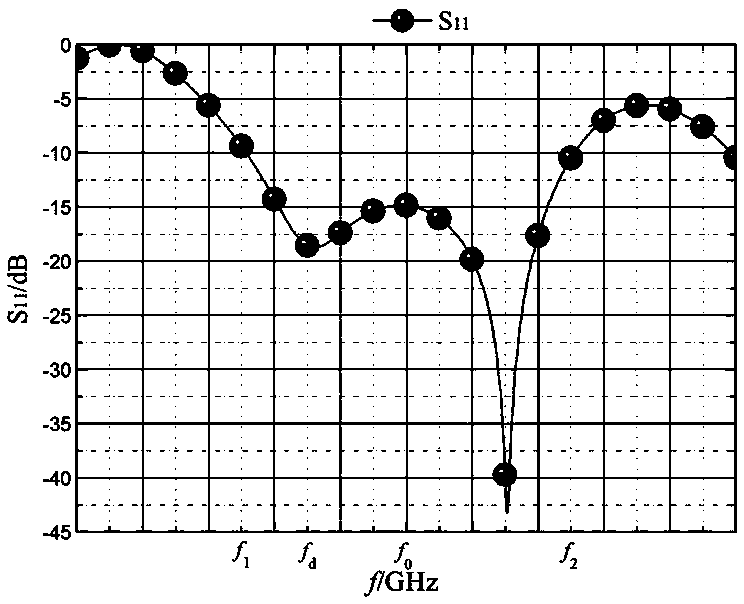
[0025] Such as figure 1 , 2 , 3, the broadband antenna for through-wall radar imaging in this embodiment includes a dielectric substrate 1 and a metal reflector 2, the dielectric substrate 1 is fixedly arranged above the metal reflector 2 through a fixed support assembly 3, and the dielectric substrate 1 The front side of the dielectric substrate 1 is printed with interconnected metal patches 4 and microstrip feeders 5 , and the back side of the dielectric substrate 1 is printed with a metal ground plate 6 with slots 61 .

[0026] For the above-mentioned antenna in this embodiment, by arranging a metal reflector 2 under the dielectric substrate 1, the dielectric substrate 1 has a certain distance between the fixed support assembly 3 and the metal reflector 2, w...


PUM

PropertyMeasurementUnit
Widthaaaaaaaaaa

Abstract

The invention discloses a broadband antenna for through-wall radar imaging. The broadband antenna comprises a dielectric substrate and a metal reflection board, wherein the dielectric substrate is fixedly arranged above the metal reflection board through a fixed support assembly; a metal patch and a micro-strip feeder line connected with the metal patch are printed on the front of the dielectric substrate; and a metal grounding plate with a slit is printed on the back of the dielectric substrate. The broadband antenna has the advantages of being simple and compact in structure, low in cost, small in size and high in gain.

Description

technical field [0001] The invention relates to the technical field of through-wall radar imaging, in particular to a broadband antenna for through-wall radar imaging. Background technique [0002] The through-wall radar can be used to detect, locate and image the target behind the wall. For example, in emergency situations such as post-disaster rescue, rescuers can use the through-wall radar to search and rescue the injured buried under the ruins, so as to gain valuable post-disaster information. Broadband imaging is the key to realizing through-wall radar detection. Compared with the conventional radar, according to the characteristics of the through-wall radar itself, the use scene and other characteristics, the antenna in the through-wall radar needs to have the characteristics of low working frequency band, wide working bandwidth, high gain, and light weight. In the frequency band, microstrip antennas usually cannot achieve broadband, high gain, and miniaturization at ...

Claims


Application Information

Patent Timeline
IPC IPC(8): H01Q19/10H01Q9/04H01Q1/38H01Q1/48H01Q1/50
CPCH01Q1/38H01Q1/48H01Q1/50H01Q9/045H01Q19/104
Inventor 袁亚超王生水
Owner HUNAN NOVASKY ELECTRONICS TECH
Learn More