
Soft-switch inverter circuit with constant common-mode voltage

A common-mode voltage, soft-switching technology, applied in the direction of high-efficiency power electronic conversion, photovoltaic power generation, electrical components, etc., can solve the problem of increasing the structural constraints of soft-switching circuits, and achieve the effect of high power density

Inactive Publication Date: 2019-03-01
SOUTHEAST UNIV
View PDF1 Cites 3 Cited by
  • Summary
  • Abstract
  • Description
  • Claims
  • Application Information

AI Technical Summary

Problems solved by technology

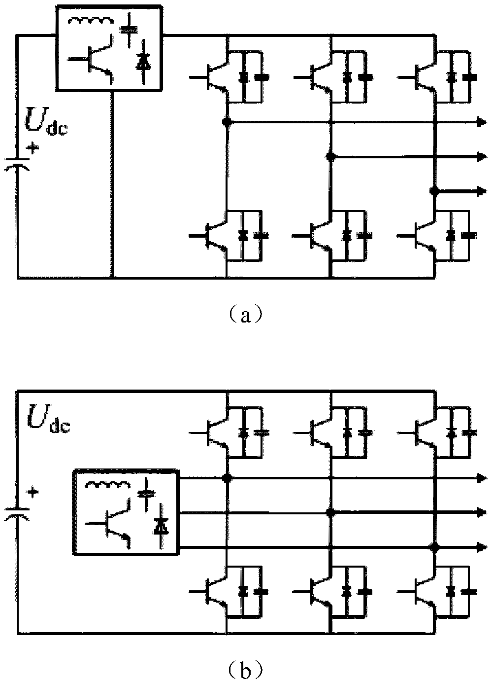
[0005] Therefore, if you want to use soft switching technology in non-isolated inverter systems, you must avoid generating common-mode voltages, which increases the constraints on the construction of soft switching circuits

Method used


Image

  • Soft-switch inverter circuit with constant common-mode voltage
  • Soft-switch inverter circuit with constant common-mode voltage
  • Soft-switch inverter circuit with constant common-mode voltage

Examples


Embodiment 1

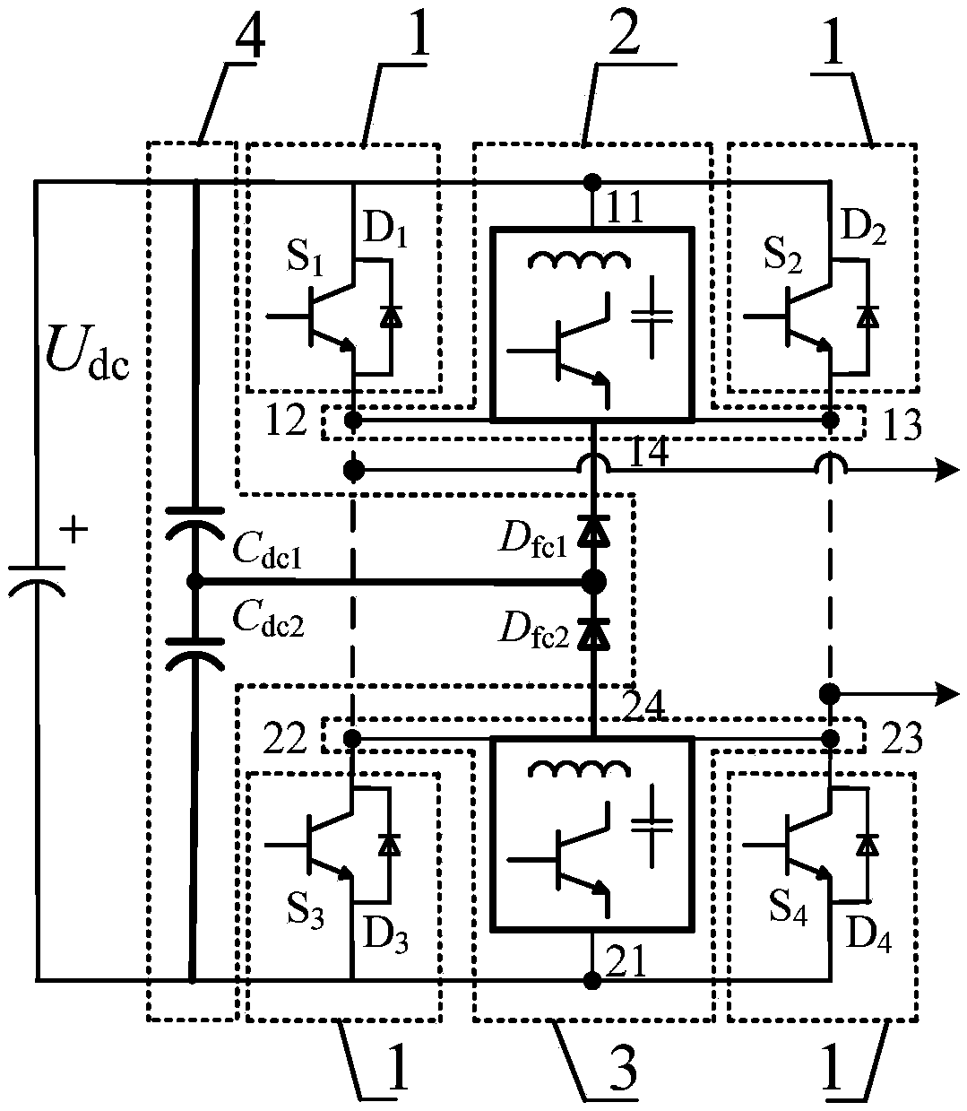
[0036] Such as Figure 5 As shown, the composition of the main circuit of Embodiment 1 of the present invention is described, and the circuit diagram of the combination of IGBT and MOSFET is used; the first power switch tube S 1 and the first power diode D 1 Parallel combination, the second power switch tube S 2 and the second power diode D 2 Parallel combination, the third power switch tube S 3 and the third power diode D 3 parallel combination and the fourth power switch S 4 and the fourth power diode D 4 The parallel combination forms the high-frequency main switching unit.

[0037] By the first auxiliary power switch tube S 1a and the first auxiliary power diode D 1a Parallel combination, the second auxiliary power switch tube S 2a and the second auxiliary power diode D 2a Parallel combination, the first auxiliary resonant capacitor C 1a , the first auxiliary resonant inductance L 1a Form positive bus polarity resonant network 2. The third auxiliary power swit...

Embodiment 2

[0042] Such as Figure 8 As shown, the composition of the main circuit of the second embodiment of the present invention is described, and the circuit diagram of the combination of IGBT and MOSFET is used; the first power switch tube S 1 and the first power diode D 1 Parallel combination, the second power switch tube S 2 and the second power diode D 2 Parallel combination, the third power switch tube S 3 and the third power diode D 3 parallel combination and the fourth power switch S 4 and the fourth power diode D 4 The parallel combination forms the high-frequency main switching unit.

[0043] By the first auxiliary power switch tube S 1a and the first auxiliary power diode D 1a Parallel combination, the first blocking power switch tube S 1b and the first blocking power diode D 1b Parallel combination, the second blocking power switch tube S 2b and a second blocking power diode D 2b Parallel combination, the first auxiliary resonant capacitor C 1a , the second au...


PUM


Abstract

The invention discloses a soft-switch inverter circuit with constant common-mode voltage. The soft-switch inverter circuit comprises a high-frequency main switch unit, a resonant network unit and a follow current clamping branch. Through adding resonant networks with polarity features of positive buses and negative buses, a soft-switch working condition taking zero voltage or zero current as a technological feature is provided for a high-frequency switch tube; and through adding a serial diode follow current branch and a DC bus voltage division branch and connecting midpoints of the two branches to form the follow current clamping branch, synchronization of the two resonant networks in the aspect of switch frequency scale is ensured and common-mode voltage clamping is realized. The soft-switch inverter circuit is capable of constructing rich circuit topologies for efficient high-power density non-isolated photovoltaic grid-connected inverters and application occasions such as electriccar variable-flow driving and the like.

Description

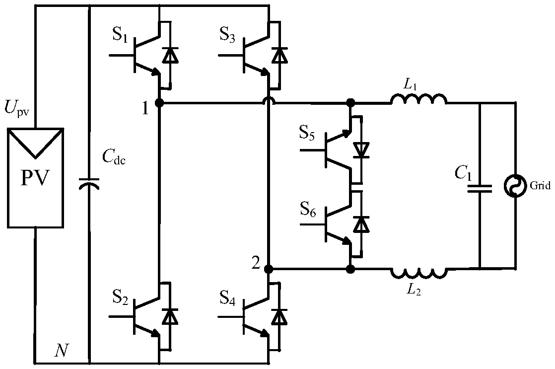
technical field [0001] The invention belongs to the technical field of inverter topology, and in particular relates to a soft-switching inverter circuit with constant common-mode voltage. Background technique [0002] Non-isolated inverter circuits, taking photovoltaic grid-connected inverters as an example, have the advantages of simple structure, high conversion efficiency and low cost, and have been widely used in the industry. Such as figure 1 As shown, it is a hard-switching inverter circuit (EP1369985A2) invented by the German Sunways company. In order to achieve higher conversion efficiency, its working switching frequency is generally low (10-20kHz); and it also requires a relatively large filter Inductors and filter capacitors, which not only increase the volume and weight of the grid-connected inverter, but also increase the cost. [0003] The most important factor limiting the improvement of conversion efficiency of non-isolated inverters is the loss of switchin...

Claims


Application Information

Patent Timeline
IPC IPC(8): H02M7/5387
CPCH02M7/5387H02M1/0058H02M1/123Y02B70/10Y02E10/56
Inventor 肖华锋王政花为程明
Owner SOUTHEAST UNIV
Features
  • Generate Ideas
  • Intellectual Property
  • Life Sciences
  • Materials
  • Tech Scout
  • Unparalleled Data Quality
  • Higher Quality Content
  • 60% Fewer Hallucinations
Learn More