Motor control circuit for intelligently sensing human body vibration
A technology of motor control and human body, applied in the field of circuits, can solve problems such as unsatisfactory swing effects without artificial intelligence, no motor control circuit, singleness, etc.
- Summary
- Abstract
- Description
- Claims
- Application Information
AI Technical Summary
Problems solved by technology
Method used
Image
Examples
Embodiment 1
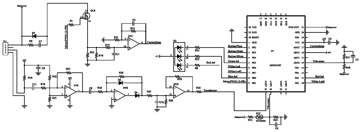
[0017] Embodiment 1, a motor control circuit for intelligently sensing human body vibrations, including an MCU module, a battery power supply module, a vibration acquisition module, a motor detection module, and a sound wave acquisition module, the battery power supply module provides a stable power supply for the MCU module, and the The vibration acquisition module and the sound wave acquisition module collect human body vibration signals and environmental sound signals respectively, the motor detection module detects the motor running state, and the MCU module receives the signals of the vibration acquisition module, the motor detection module and the sound wave acquisition module;
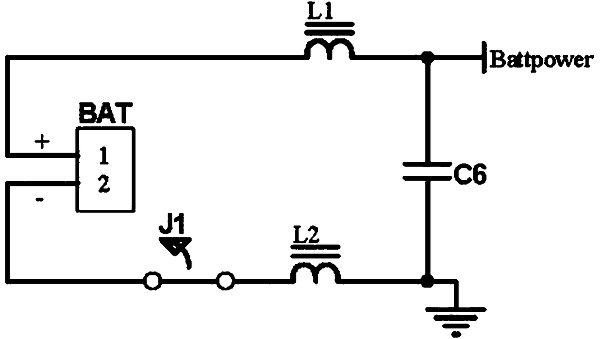
[0018] The battery power supply module receives the mains voltage through the power terminal BAT to charge the battery voltage Battpower. When charging, the power switch J1 is normally closed. Filter out the high-frequency clutter in the signal, the positive pole of the power terminal BAT is conn...
Embodiment 2
[0022] Embodiment 2. On the basis of Embodiment 1, the motor detection module judges the abnormality of the output power signal of the motor TN1. When the motor TN1 is abnormally blocked, the output power signal of the motor TN1 pin 1 is abnormal. At this time, the MOS tube Q1A is turned on, one way is input to pin 9 of MCU P1, and the power signal of motor TN1 at this time is analyzed, and the other way is filtered by the filter circuit composed of resistor R14-resistor R16 and capacitor C1, and then input to the MCU after being in-phase amplified by op amp U1C Pin 17 of P1 is the alarm signal of the single-chip microcomputer P1, which can trigger the single-chip microcomputer P1 to send an alarm signal to the external alarm module. One end of the resistor R9 is connected to the battery voltage Battpower and the negative pole of the diode D1, pin 1 of the motor TN1, and the terminal of the resistor R9 The other end is connected to one end of the capacitor C7, the other end of ...
Embodiment 3
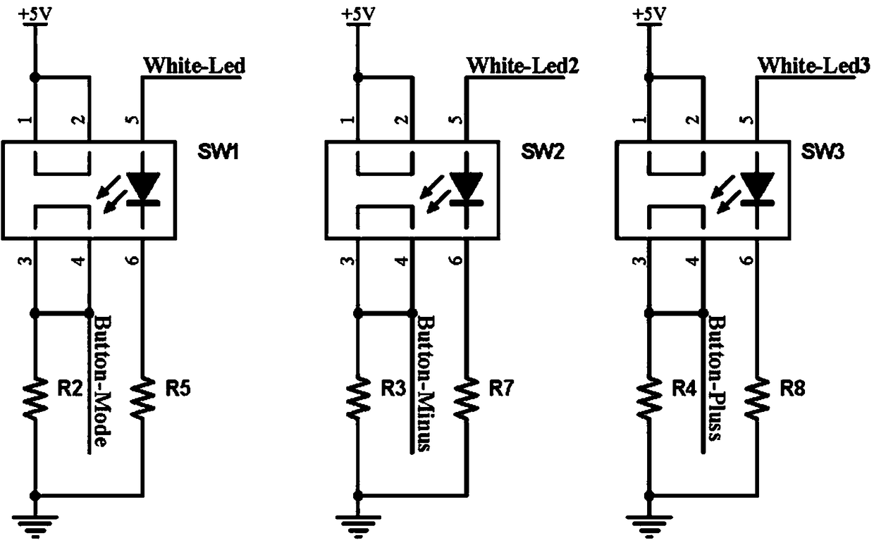
[0023]Embodiment 3, on the basis of Embodiment 2, the control circuit also includes a button module, and the button module realizes the intelligent adjustment of the motor speed through the illuminated switch SW1, the illuminated switch SW2 and the illuminated switch SW3, and the illuminated switch SW1 , The conduction of the illuminated switch SW2 and the illuminated switch SW3 is controlled by the single-chip microcomputer P1, which are adjusted in 5 levels respectively. The first level is only the lighted switch SW1 is turned on, the second level is only the lighted switch SW2 is turned on, and the third level is only The lighted switch SW3 is on, the fourth gear is only the lighted switches SW1 and SW2 are on, the fifth gear is the lighted switches SW1, SW2 and SW3 are on, controlled by the pin 3, pin 4 and pin 7 of the single chip microcomputer P1, with light Contact 1 of switch SW1 is connected to contact 2 of lighted switch SW1 and power supply +5V, contact 5 of lighted ...
PUM
 Abstract
Description
Claims
Application Information
 - R&D
- Intellectual Property
- Life Sciences
- Materials
- Tech Scout
- Unparalleled Data Quality
- Higher Quality Content
- 60% Fewer Hallucinations
Browse by: Latest US Patents, China's latest patents, Technical Efficacy Thesaurus, Application Domain, Technology Topic, Popular Technical Reports.
© 2025 PatSnap. All rights reserved.Legal|Privacy policy|Modern Slavery Act Transparency Statement|Sitemap|About US| Contact US: help@patsnap.com


