Cooling device

A technology of cooling device and air cooling device, applied in the field of rail transit, can solve the problems of low life, high noise of heat dissipation cooling device, complex structure, etc., and achieve the effect of reducing noise, ensuring comfort, and reducing volume

Pending Publication Date: 2019-03-01
HUNAN LIANCHENG TRACK EQUIP CO LTD
View PDF13 Cites 5 Cited by
  • Summary
  • Abstract
  • Description
  • Claims
  • Application Information

AI Technical Summary

Problems solved by technology

[0004] (1) Both the water pump and the fan are of a single design, if any one of them fails, it will directly affect the normal operation of the train;
[0005] (2) The heat dissipation and cooling device is noisy during operation, which affects the comfort of the train;
[0006] (3) The motor of the fan is prone to overheating under the radiation of high-temperature gas, which affects the normal operation of the fan and increases the frequency of maintenance;
[0007] (4) The cooling oil is easy to enter the dryer due to the vibration caused by the train operation, resulting in abnormal operation of the dryer;
[0008] (5) Ordinary rubber damping pads are used between the cooling device and the train, which has a low service life and needs to be replaced regularly. The cost of the whole life cycle is high and the vibration isolation effect is poor, which affects the comfort of the train
[0009] (6) The expansion water tank is equipped with a main chamber and an auxiliary chamber, double conduits, the structure is complex, the manufacturing process is difficult, the cost is high, and it is easy for the expansion water tank to fail to inhale normally because the auxiliary chamber is not effectively sealed

Method used


Image

  • Cooling device
  • Cooling device
  • Cooling device

Examples


Embodiment 1

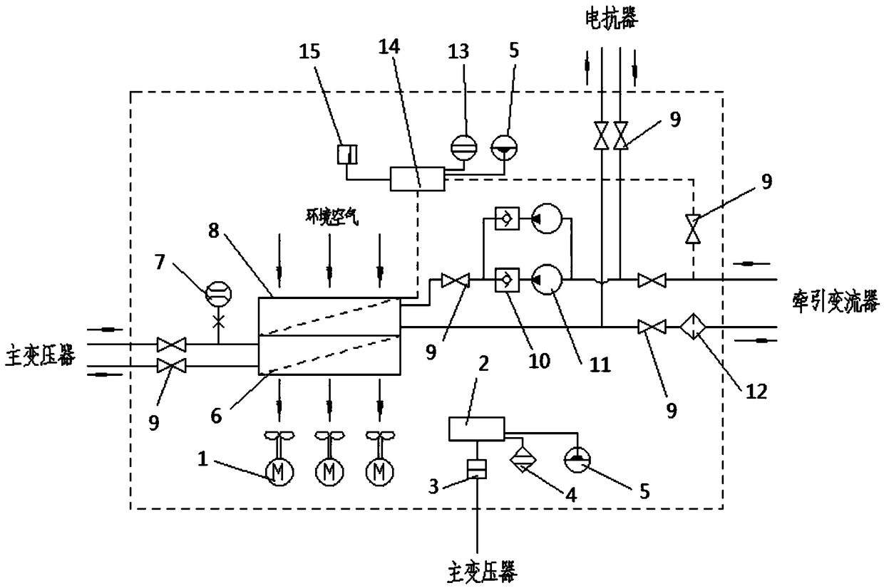
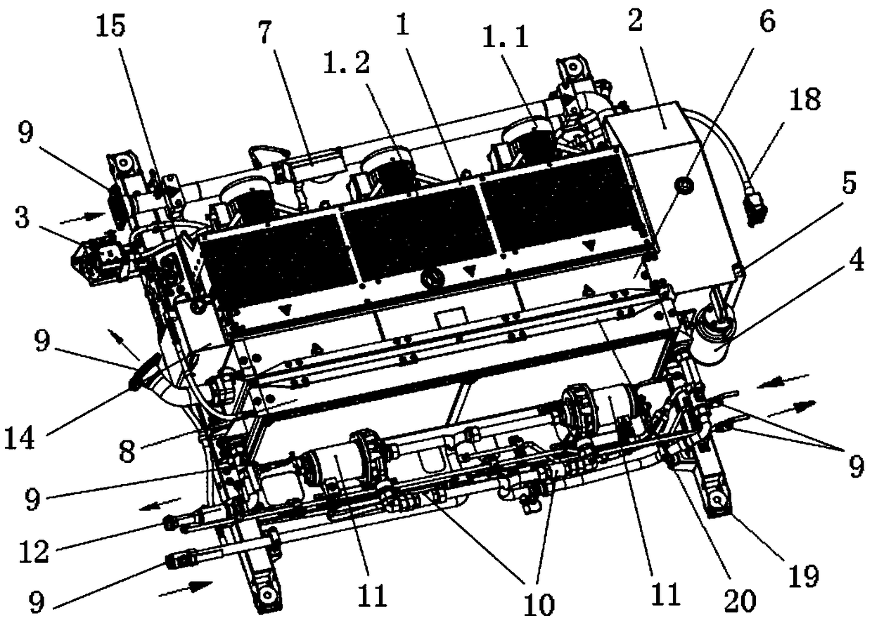
[0052] see Figure 1-8 , a cooling device, comprising a water cooling circuit, an oil cooling circuit and an air cooling device, the water cooling circuit is used for cooling the reactor and the traction converter, the oil cooling circuit is used for cooling the main transformer, the The air cooling device is used for cooling the cooling medium in the water cooling circuit and oil cooling circuit;

[0053] The air-cooling device includes at least two cooling fans 1 arranged in parallel. The cooling fan 1 includes a motor 1.1 and a fan impeller 1.2. The fan impeller 1.2 is arranged on the output shaft of the motor 1.1 to be driven by the motor 1.1. Rotation; the fan impeller is a sawtooth impeller, wherein the ratio of the tooth width T to the tooth height H is 0.25≤T / H≤0.5, see details Image 6 (a) and Image 6 (b).

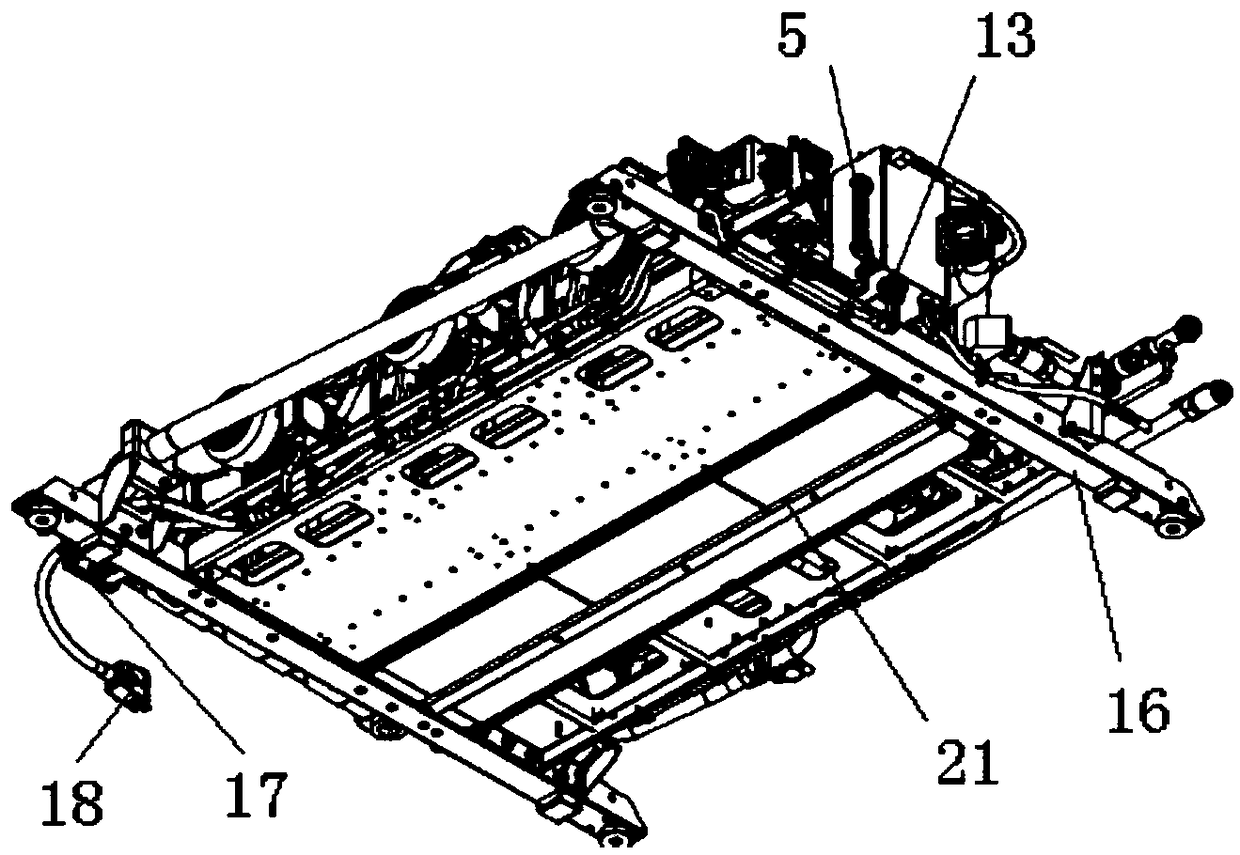
[0054] see Figure 5 , the output shaft end of the motor 1.1 can be detachably provided with a front end cover 1.10, the front end cover and the output shaft...


PUM


Abstract

The invention provides a cooling device. The cooling device comprises a water cooling circuit, an oil cooling circuit and an air cooling device, wherein the water cooling circuit is used for cooling an electric reactor and a traction converter; the oil cooling circuit is used for cooling a main transformer; and the air cooling device is used for cooling the cooling mediums in the water cooling circuit and the oil cooling circuit. The cooling device has the benefits that the condition that the cooling device cannot be operated normally as any one of a fan and a water pump breaks down due to single design of the fan and the water pump is effectively solved; the noise is effectively reduced, the comfort of a train is ensured and the service life of the motor is prolonged through improving thecooling fan; cooling oil can be effectively prevented from entering a dryer to disturb the normal work of the dryer through improving the structure of an expansion oil tank and the mounting manner ofthe dryer; and the expansion water tank is a single cavity structure so that the structure is simpler and more reliable and cavitation can be effectively prevented.

Description

technical field [0001] The invention relates to the technical field of rail transit, in particular to a cooling device. Background technique [0002] Traction converters, main transformers and reactors are the key components on the train, providing power for the normal operation of the train. During the operation of the train, the traction converter, the main transformer and the reactor will generate a lot of heat, and serious consequences will be caused if the heat cannot be dissipated in time. Therefore, how to achieve stable and reliable heat dissipation for the traction converter, main transformer and reactor is particularly important. [0003] The following problems exist in the existing heat dissipation cooling device: [0004] (1) The water pump and the fan are of a single design, if any one of them has a problem, it will directly affect the normal operation of the train; [0005] (2) The noise of the cooling device is relatively loud during operation, which affect...

Claims


Application Information

Patent Timeline
Patent Type & Authority Applications(China)
IPC IPC(8): H05K7/20H01F27/12H01F27/16H01F27/08
CPCH05K7/20136H05K7/20218H01F27/085H01F27/12H01F27/16
Inventor 谭发程吴凯屈小章李丹丹刘一福栾烨罗萌
Owner HUNAN LIANCHENG TRACK EQUIP CO LTD
Why Eureka
Try Eureka