
Distributed light manipulation over imaging waveguide

A technology of waveguide and light distribution, applied in the coupling of optical waveguide, light guide, optics, etc., can solve the problems of complex visual perception system

Inactive Publication Date: 2019-03-01
MAGIC LEAP INC
View PDF10 Cites 14 Cited by
  • Summary
  • Abstract
  • Description
  • Claims
  • Application Information

AI Technical Summary

Problems solved by technology

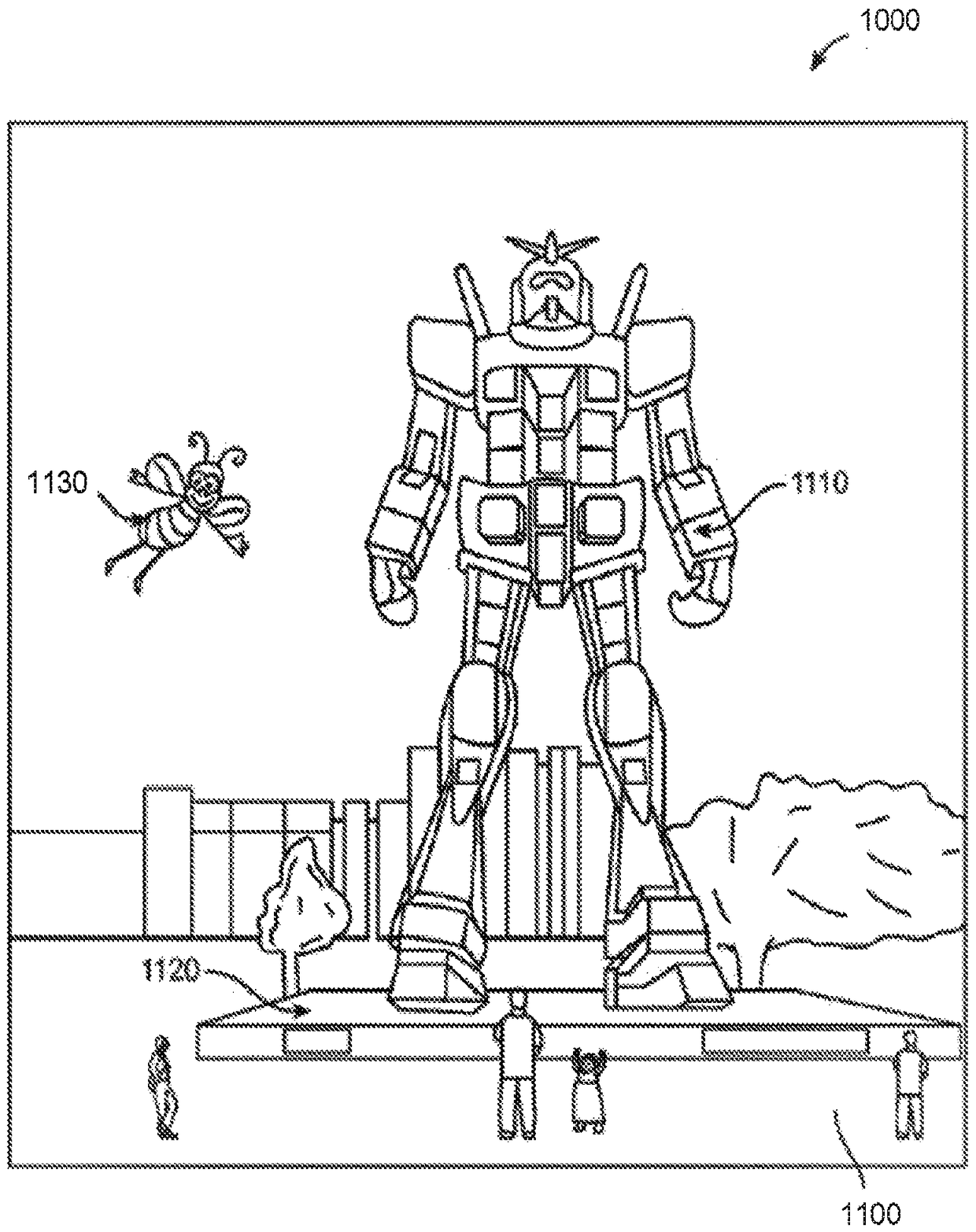
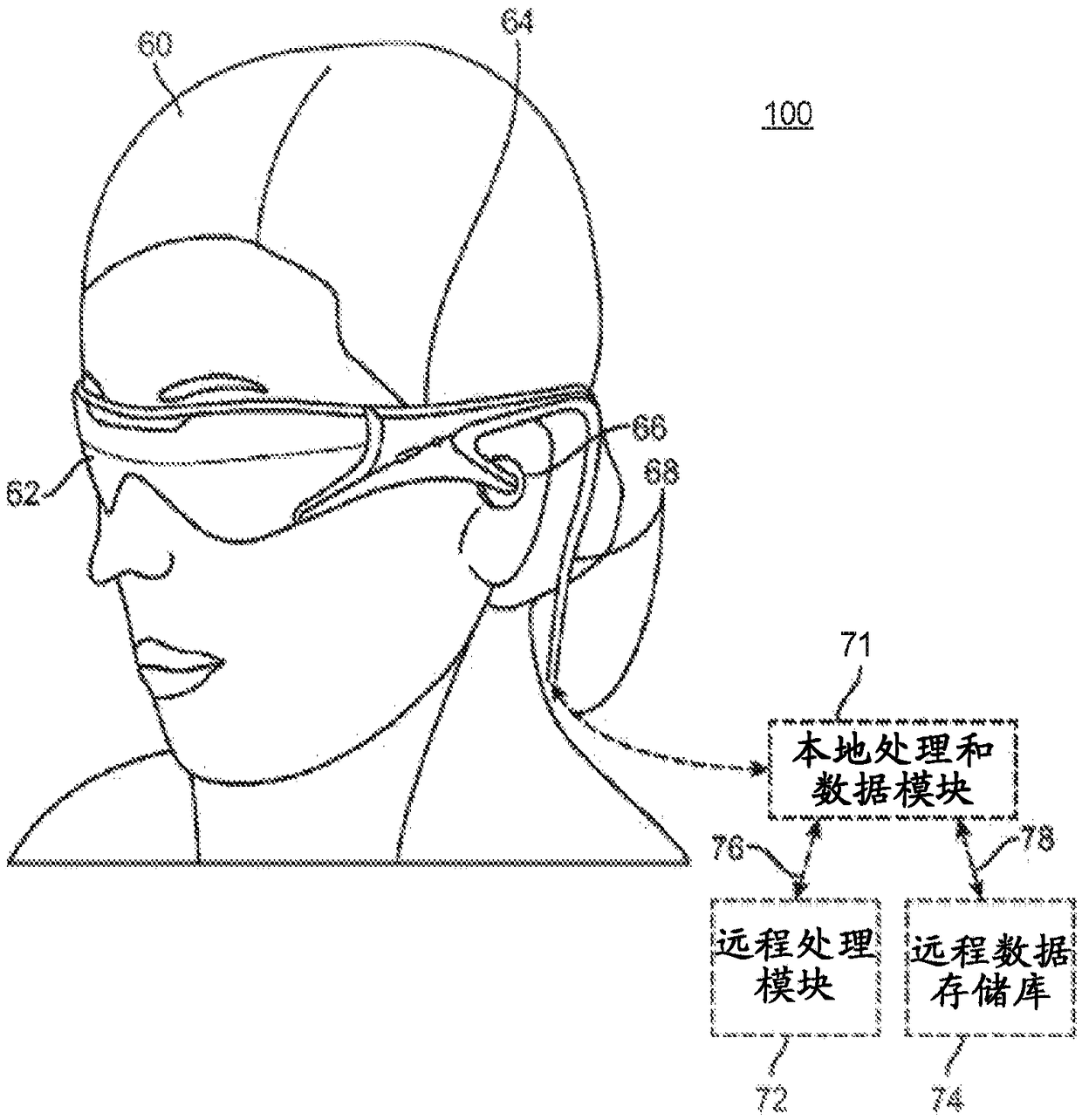
It turns out that the human visual perception system is very complex, and it is very challenging to develop VR or AR technology that facilitates the comfortable, natural feeling and rich rendering of virtual image elements among other virtual or real world image elements.

Method used


Image

  • Distributed light manipulation over imaging waveguide
  • Distributed light manipulation over imaging waveguide
  • Distributed light manipulation over imaging waveguide

Examples


Embodiment Construction

[0032] overview

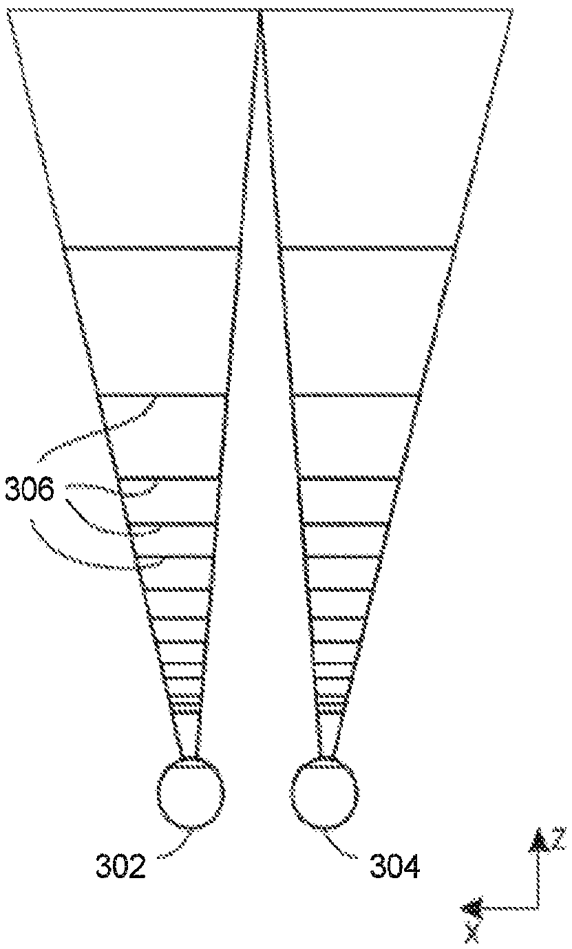
[0033] In order for a three-dimensional (3D) display to produce a realistic perception of depth, and more specifically, a simulated surface perception of depth, each point in the display's field of view needs to generate an accommodation response corresponding to its virtual depth. If the accommodative response to a displayed point does not correspond to the virtual depth of that point, as determined by convergence and binocular depth cues for stereopsis, the human eye may experience an accommodation conflict, resulting in erratic imaging, unwanted eye fatigue, Headaches, and, in the absence of regulatory information, an almost complete lack of surface depth.

[0034]VR and AR experiences can be provided by display systems having displays in which images corresponding to multiple depth planes are presented to the viewer. The images can be different for each depth plane (e.g., providing a slightly different rendering of the scene or objects) and can be indi...


PUM


Abstract

In a stacked waveguide assembly, the waveguides can comprise color filters, distributed filters, and / or switch materials. Examples of color filters include dyes, tints, or stains. Examples of distributed filters and / or switch materials include dichroic filters, Bragg gratings, electronically switchable glass, and electronically switchable mirrors. Switch materials can be designed or tuned to attenuate light of unwanted colors or wavelengths. The waveguides may each be associated with a particular design wavelength. This can mean that a waveguide that is associated with a design wavelength includes an incoupling optical element is configured to deflect light at the design wavelength to an associated light distributing element and that the associated wavelength selective region is configuredto attenuate light not at the design wavelength.

Description

[0001] Cross References to Related Applications [0002] This application asserts under 35 U.S.C. §119(e) Serial No. 62 / 335,22, filed May 12, 2016, entitled "DISTRIBUTED LIGHT MANIPULATION OVER IMAGING WAVEGUIDE" and the U.S. Provisional Application Serial No. 62 / 335,232, filed May 12, 2016, entitled "WAVELENGTH MULTIPLEXING IN WAVEGUIDES" (Wavelength Multiplexing in Waveguides), both of which The entire content of the application is hereby incorporated by reference. technical field [0003] The present disclosure relates to virtual reality and augmented reality imaging and visualization systems, and more particularly to distributing light to different waveguide regions. Background technique [0004] Modern computing and display technologies have facilitated the development of systems for so-called "virtual reality" or "augmented reality" experiences, in which a digitally reproduced image, or a portion thereof, is presented to a user in such a way that it appears or can be ...

Claims


Application Information

Patent Timeline
Patent Type & Authority Applications(China)
IPC IPC(8): G02B6/00G02B27/00G02B27/01G02B27/42
CPCG02B6/0026G02B6/005G02B6/0035G02B6/0031G02B6/0083G02B27/0172G02B6/0016G02B6/0076G02B6/0056G02B5/20G02B2027/0127G02B2027/0174G02B26/0808G02B2027/0178G02B6/34G02B2027/0114G02B2027/0125G02B2027/0112G02B2027/012
Inventor I·L·约L·E·埃德温J·G·麦克纳马拉
Owner MAGIC LEAP INC
Learn More