
Deployment or utility vehicle for limited access area of operation

A technology for emergency tasks and operating vehicles, applied in the arrangement of multiple different prime movers, vehicle components, vehicle energy storage, etc. and maintenance simple effect

Inactive Publication Date: 2019-03-05
FRAPORT AG
View PDF0 Cites 0 Cited by
  • Summary
  • Abstract
  • Description
  • Claims
  • Application Information

AI Technical Summary

Problems solved by technology

The maintenance costs in this respect are correspondingly high

Method used


Image

  • Deployment or utility vehicle for limited access area of operation
  • Deployment or utility vehicle for limited access area of operation
  • Deployment or utility vehicle for limited access area of operation

Examples


Embodiment Construction

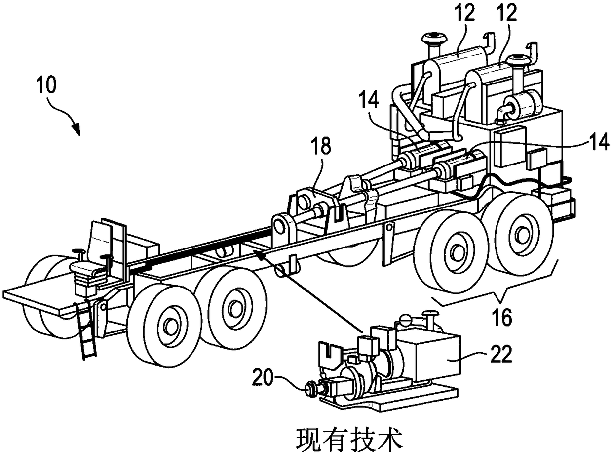
[0052] exist figure 1 The chassis 10 of a current airport fire truck is shown in an example. Two diesel engines 12 serving as drive motors of the vehicle are likewise arranged in the rear section 16 of the vehicle with two associated automatic transmissions 14 . Furthermore, an arrangement of a common transmission 18 and a fire fighting rotary pump 20 is shown, which is driven by another diesel engine (pump motor) 22 .

[0053] In the fire truck according to the present invention according to the first embodiment Figure 2 to Figure 4 In the chassis 24 shown in , two serial electric motors 26 (traction engines) are provided instead of two diesel drive motors. The power of the electric motor 26 is in the range of approximately 100 kW to 300 kW. Force is transmitted from the electric drive motor 26 to a common transmission 28 and a transfer case 40 from which the axles of the vehicle are driven.

[0054] The electrical energy for the electric drive motor 26 is provided by a ...


PUM


Abstract

An application or utility vehicle for a spatially limited area of use comprises at least one electric motor (26) for driving the vehicle, at least one accumulator (30) for providing electrical energyfor the electric motor (26) and at least one internal combustion engine (32), in particular a diesel engine for driving at least one working machine (34) associated with the utility or commercial vehicle. The internal combustion engine (32) is also set up to charge the accumulator (30).

Description

technical field [0001] The invention relates to an emergency vehicle or service vehicle for use in areas of limited space, in particular an airport firefighting vehicle. Background technique [0002] “Emergency vehicles or operating vehicles for use in space-restricted areas” are understood to be vehicles which are intended to be used only within fixed areas, such as for example at airports or industrial company premises. [0003] Airport operators must provide a sufficient number of fire trucks to ensure fire safety according to the legal regulations based on the international agreement ICAO (International Civil Aviation Organization) or within the EU according to the regulations of the European Union Aviation Safety Administration (EASA). [0004] Currently, a typical airport fire truck has one or two powerful diesel engines that meet different exhaust emission standards depending on the given year. Power is transmitted from the drive motor via one or two automatic transm...

Claims


Application Information

Patent Timeline
Patent Type & Authority Applications(China)
IPC IPC(8): B60K6/26B60K6/46B60K6/52B60L1/00A62C27/00
CPCA62C27/00B60K6/26B60K6/46B60K6/52B60L1/00B60L1/003B60L1/20B60L50/61B60L58/21B60L2200/40B60L2220/42B60W2300/12Y02T10/62Y02T10/64Y02T10/70
Inventor 马库斯·梅茨勒
Owner FRAPORT AG
Learn More