
Rotary valve type pressure pulse generator

A pressure pulse and generator technology, applied in the field of rotary valve pressure pulse generators, can solve the problems of inability to generate effective pressure pulse amplitude, affecting pulse pressure amplitude, etc.

Pending Publication Date: 2019-03-05
CHINA PETROLEUM & CHEM CORP +1
View PDF1 Cites 3 Cited by
  • Summary
  • Abstract
  • Description
  • Claims
  • Application Information

AI Technical Summary

Problems solved by technology

The use of drilling pulse generators in water injection wells is subject to the following limitations: 1) The displacement of water injection wells is much smaller than that of drilling mud, which cannot generate effective pressure pulse amplitudes for ground identification; Pressure affects the pulse pressure amplitude; 3) The pulse generator must have a hollow channel to meet the needs of the test instrument; 4) Due to the size limit of the water injection well casing, the outer diameter of the pulse generator should be less than 115mm; 5) It needs to be placed in the water injection wellbore for a long time Medium work, the service life should meet the needs of the water well inspection cycle of more than 3 years

Method used


Image

  • Rotary valve type pressure pulse generator
  • Rotary valve type pressure pulse generator
  • Rotary valve type pressure pulse generator

Examples


Embodiment Construction

[0025] The detailed description and technical content of the present invention are described below with the drawings, but the drawings are only for reference and description, and are not used to limit the present invention.

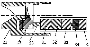
[0026] as attached Figure 1-3 As shown, a rotary valve type pressure pulse generator includes a cylinder structure composed of an upper joint 1, an outer cylinder 6, and a lower joint 7 in sequence. An overflow channel is formed inside the cylinder structure, and a rotary valve 2 is also included. The rotary valve is installed inside the cylinder structure. The rotary valve includes a stator 21, a rotor 22, and a main shaft 23. The stator has a flow hole, and the rotor is fixed on the main shaft. The hole changes the flow area.

[0027] A drive mechanism is also provided inside the cylinder structure, and the power output end of the drive mechanism is connected to the main shaft of the rotary valve. The rotor is connected with a reducer through a main ...


PUM


Abstract

The invention discloses a rotary valve type pressure pulse generator. The pressure pulse generator is a cylinder structure formed by sequentially connecting an upper joint, an outer cylinder and a lower joint, and a flow passing channel is formed inside the cylinder structure; the pressure pulse generator is characterized in that the generator also includes a rotary valve, and the rotary valve isinstalled in the cylinder structure; the rotary valve includes a stator, a rotor and a main shaft; the stator is provided with a flow passing hole; the rotor is fixed on the main shaft, and the rotorrotates around the main shaft to change the flow passing area of the flow passing hole on the stator; and a sheath is installed on the inner wall of the cylinder structure in an offset manner. A driving mechanism is further disposed inside the cylinder structure, and a power output end of the driving mechanism is connected to the main shaft of the rotary valve. The rotor is connected to a speed reducer through a main shaft, and the driving mechanism includes the speed reducer, a magnetic coupling, a flexible coupling, and a motor that are sequentially connected. The rotary valve type pressurepulse generator achieves transmission of pressure pulse signals to a well head.

Description

technical field [0001] The invention relates to the field of oil field water injection technology, in particular to a rotary valve type pressure pulse generator. Background technique [0002] In recent years, with the continuous improvement of the separate injection technology of water injection wells, the testing and deployment technology of water wells has also developed rapidly, from conventional steel wire throwing and fishing testing and adjustment to mechatronic integration testing and adjustment and intelligent completion and separate injection. With the advancement of micro-motor and automation technology, research on intelligent measurement and adjustment technology has been carried out in the field of oilfield water well injection, and the direction of development is from cable transmission to wireless transmission. At present, the downhole cable transmission technology is relatively mature. The signal parameters between the ground and downhole instruments are tran...

Claims


Application Information

Patent Timeline
IPC IPC(8): E21B47/18
CPCE21B47/18
Inventor 王增林马珍福崔玉海张凯孙金峰唐高峰刘晋伟王宏万李永康张卫卫
Owner CHINA PETROLEUM & CHEM CORP
Learn More