Optical lens

An optical lens and lens technology, applied in the field of optical lens, can solve problems such as dispersion deterioration, reduced lens performance, difficulty, etc., and achieve the effects of high thermal stability, small FNO, and small distortion

Active Publication Date: 2019-03-05
NINGBO SUNNY AUTOMOTIVE OPTECH
View PDF5 Cites 0 Cited by
  • Summary
  • Abstract
  • Description
  • Claims
  • Application Information

AI Technical Summary

Problems solved by technology

[0004] However, for a lens with a small Fno (~1.2 or so), it directly makes it difficult to achieve the small dispersion of the usual imaging lens. For such a lens with a small Fno, the diffuse spot is generally controlled within half the pixel size, for example : For a lens with a pixel size of 100um, the diffuse spot should be controlled within 50um
In actual production, it is inevitable to introduce various tolerances, so the dispersion becomes worse, and the received energy of the pixel is weakened, thereby reducing the performance of the lens; when the ambient temperature changes, the lens is deformed, and the best image plane deviates from the position of the chip, which will also cause the reception Poor end lens performance

Method used


Image

  • Optical lens
  • Optical lens
  • Optical lens

Examples


no. 1 example

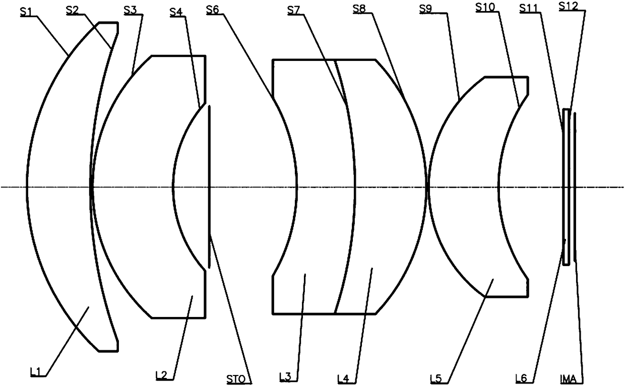
[0109] Such as figure 1As shown, the optical lens according to the first embodiment of the present invention includes in sequence from the object side to the image side: a meniscus-shaped first lens L1 with positive refractive power, a first surface S1 convex to the object side and a concave image The second surface S2 on the side; the meniscus-shaped second lens L2 with negative power, with the first surface S3 convex to the object side and the second surface S4 concave to the image side; stop STO; with negative light The meniscus-shaped third lens L3 of focal power has a first surface S6 concave to the object side and a second surface S7 convex to the image side; a meniscus-shaped fourth lens L4 with positive refractive power has a concave direction The first surface S7 on the object side and the second surface S8 convex to the image side, the fourth lens L4 and the third lens L3 are cemented lenses; the meniscus-shaped fifth lens L5 with positive power has a convex directio...

no. 2 example

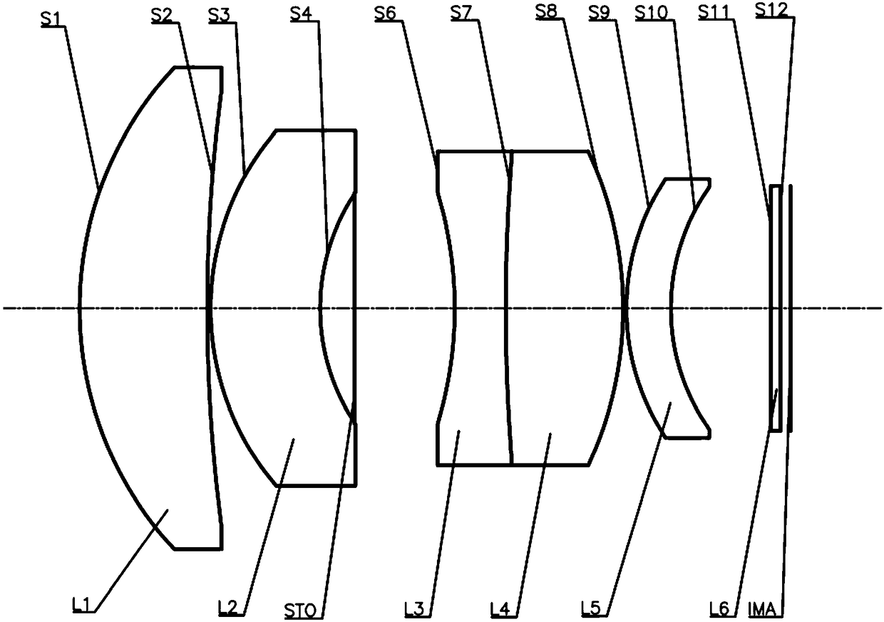
[0122] Such as figure 2 As shown, the optical lens according to the second embodiment of the present invention includes in sequence from the object side to the image side: a meniscus-shaped first lens L1 with positive refractive power, a first surface S1 convex to the object side and a concave image The second surface S2 on the side; the meniscus-shaped second lens L2 with negative power, with the first surface S3 convex to the object side and the second surface S4 concave to the image side; stop STO; with negative light The third lens L3 of the biconcave shape of power has the first surface S6 concave to the object side and the second surface S7 concave to the image side; the fourth lens L4 of the biconvex shape with positive refractive power has a convex direction The first surface S7 on the object side and the second surface S8 convex to the image side, the fourth lens L4 and the third lens L3 are cemented lenses; the meniscus-shaped fifth lens L5 with positive power has a...

no. 3 example

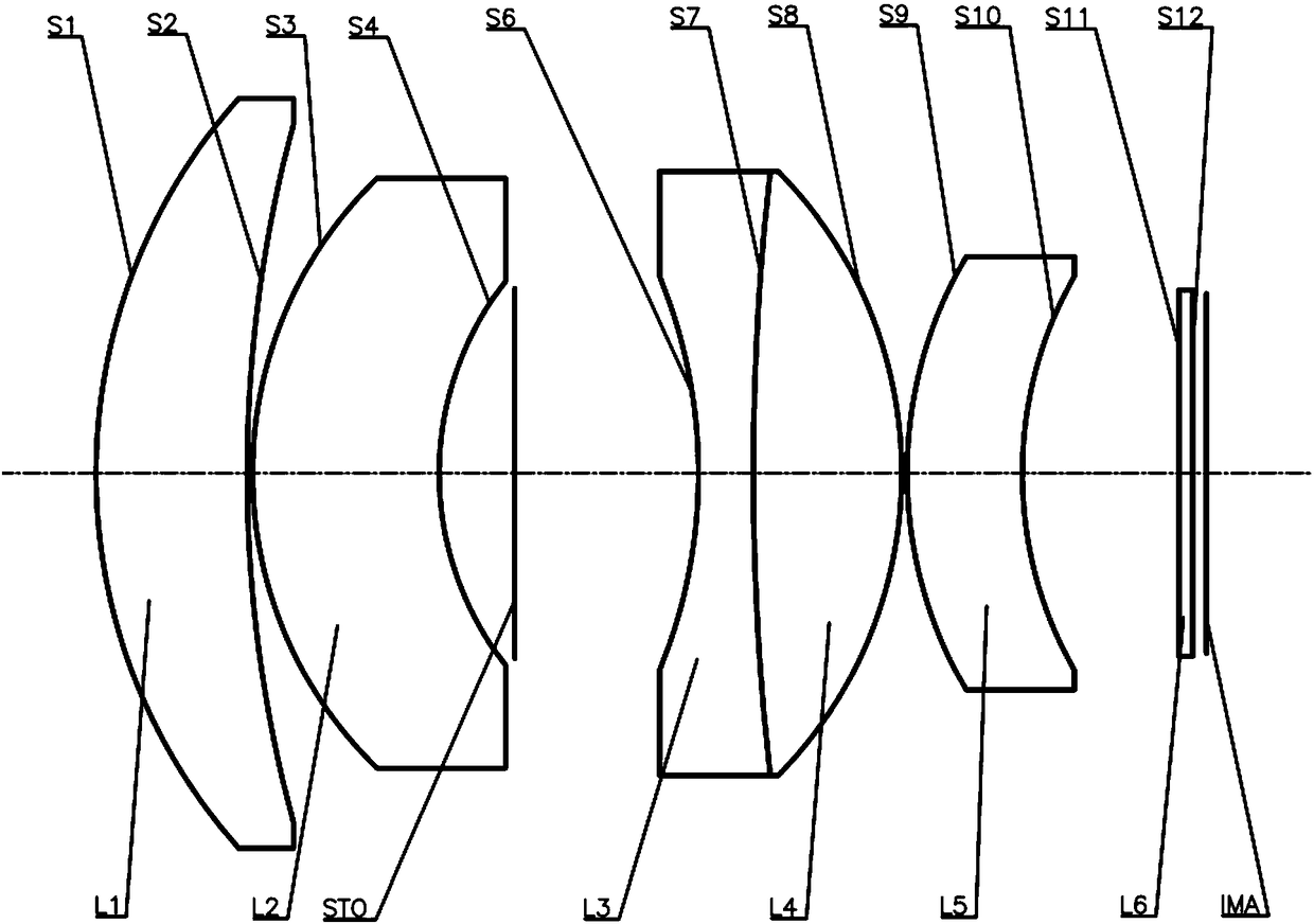
[0135] Such as image 3 As shown, the optical lens according to the third embodiment of the present invention includes in sequence from the object side to the image side: a meniscus-shaped first lens L1 with positive refractive power, a first surface S1 convex to the object side and a concave image The second surface S2 on the side; the meniscus-shaped second lens L2 with negative power, with the first surface S3 convex to the object side and the second surface S4 concave to the image side; stop STO; with negative light The third lens L3 of the biconcave shape of power has the first surface S6 concave to the object side and the second surface S7 concave to the image side; the fourth lens L4 of the biconvex shape with positive refractive power has a convex direction The first surface S7 on the object side and the second surface S8 convex to the image side, the fourth lens L4 and the third lens L3 are cemented lenses; the meniscus-shaped fifth lens L5 with positive power has a c...


PUM


Abstract

The invention provides an optical lens. The optical lens comprises a first lens, a second lens, a third lens, a fourth lens and a fifth lens in sequence from the object side to the image side, whereinthe first lens has positive focal power; the second lens is a meniscus lens with negative focal power, the object side surface is a convex surface, and the image side surface is a concave surface; the third lens has negative focal power; the fourth lens has positive focal power; and the fifth lens is a meniscus lens with positive focal power, the object side surface is a convex surface, and the image side surface is a concave surface. The optical lens provided by the invention can achieve small FNO, small distortion, low cost and high thermal stability while maintaining lens miniaturization through optimally setting the shape of each lens and reasonably distributing the focal power of each lens.

Description

technical field [0001] The invention relates to the field of optical lenses, in particular to an optical lens capable of at least achieving small FNO, small distortion, low cost and high thermal stability while ensuring miniaturization. Background technique [0002] For some lenses, it is necessary to collect as much light as possible so that the image sensor chip behind the lens can receive most of the energy of the incident light. Therefore, this kind of lens requires a small FNO, so that the lens can receive more light, and the requirement for distortion is also high. [0003] Here, FNO refers to the ratio of the focal length to the clear aperture, which reflects the amount of light transmitted by the lens. The smaller the FNO value, the larger the aperture, and the larger the light transmission of the lens. [0004] However, for a lens with a small Fno (~1.2 or so), it directly makes it difficult to achieve the small dispersion of the usual imaging lens. For such a len...

Claims


Application Information

Patent Timeline
Patent Type & Authority Applications(China)
IPC IPC(8): G02B13/00
CPCG02B13/0045
Inventor 徐超张绍鹏杨佳俞洪涛
Owner NINGBO SUNNY AUTOMOTIVE OPTECH
Why Eureka
Try Eureka