Interconnecting assembly for motor

A component and winding technology used in the field of interconnected components

Inactive Publication Date: 2019-03-05
ZF FRIEDRICHSHAFEN AG
View PDF6 Cites 0 Cited by
  • Summary
  • Abstract
  • Description
  • Claims
  • Application Information

AI Technical Summary

Problems solved by technology

The invention solves this task by means of the subject matter of the independent claims

Method used


Image

  • Interconnecting assembly for motor
  • Interconnecting assembly for motor
  • Interconnecting assembly for motor

Examples


Embodiment Construction

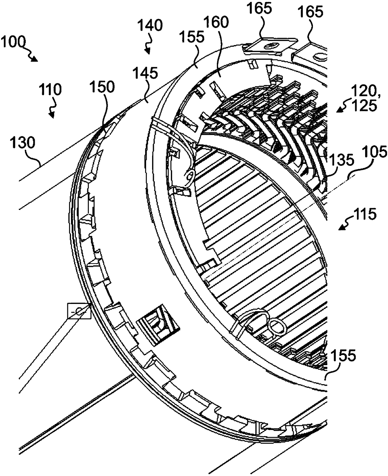
[0031] figure 1 An exemplary electric machine 100 is shown, which comprises an axis of rotation 105 about which a stator 110 is arranged relative to a rotatably mounted rotor 115 (not shown). In this document, the descriptions of polarity always refer to the axis of rotation 105 of the electric machine 100 unless otherwise stated. The electric machine 100 is designed as a permanent magnet synchronous machine by way of example with a radially outer stator 110 and an inner rotor 115 , but other embodiments are also conceivable.

[0032] A plurality of windings 120 are arranged on the stator 110 , which are each assigned to one of the three phases 125 . Winding 120 is preferably designed as a hairpin winding with hairpin elements 135 . The hairpin element 135 is bent substantially in a U-shape and includes two conductor segments spaced apart from each other and a bend section therebetween. The magnetic conducting element 130 can in particular be configured as an axial stack of...


PUM


Abstract

The invention relates to a motor (100) comprising a plurality of phases (125), wherein each phase (125) is provided with a winding (120). The interconnecting assembly (140) includes: an annular support member (150) having a plurality of axial voids (310) for respectively routing a section of the winding (120); and a plurality of concentrically disposed, hollow cylindrical switching rings (145), wherein each switching ring (145) is configured to contact the winding (120). The annular support element ( 150 ) and the switching ring ( 145 ) are configured to engage one another in a shape locking manner in the radial direction.

Description

technical field [0001] The invention relates to an interconnection assembly for an electric motor. In particular, the invention relates to an interconnection arrangement for electrically contacting winding sections of the electrical machine. Background technique [0002] The electric machine comprises a stator and a rotor, which are mounted rotatably relative to one another about an axis of rotation. The stator comprises a plurality of laminations which are stacked axially and which have axial grooves in which the conductor segments of the windings lie. The current flowing through the conductor segments is to be conducted to the electrical connection by means of the interconnection assembly. For this purpose, complex contacting or conductor guides between the conductor segments may be required and the collecting or distributing elements for the current may be difficult to handle. [0003] Document JP 2016 032 392 A relates to an interconnection assembly with hairpin windi...

Claims


Application Information

Patent Timeline
Patent Type & Authority Applications(China)
IPC IPC(8): H02K3/50
CPCH02K3/50H02K2203/09H02K3/52H02K5/225H02K1/16H02K3/14H02K3/24H02K15/0062H02K15/0087
Inventor K·维拉克C·维德尔J·维特曼R·林德武尔姆R·维特斯塔特D·施米特M·库多科B·布齐奥A·沙夫莱恩M·范海登
Owner ZF FRIEDRICHSHAFEN AG
Why Eureka
Try Eureka