Micro-strip energy collector and broadband fluid energy collector

An energy harvester, microstrip technology, applied in electrical components, piezoelectric effect/electrostrictive or magnetostrictive motors, generators/motors, etc., can solve the problem of narrow working bandwidth, low output voltage/power, difficult Meet the requirements of energy storage and driving devices, and achieve the effect of increasing the flow rate and reducing the difficulty of collection

Inactive Publication Date: 2019-03-05
青岛因菲尼思微电子科技有限公司
View PDF7 Cites 2 Cited by
  • Summary
  • Abstract
  • Description
  • Claims
  • Application Information

AI Technical Summary

Problems solved by technology

[0004] At present, most vibration energy harvesters based on the piezoelectric effect have some disadvantages: (1) the output voltage / power of the existing piezoelectric energy harvesters is too low to meet the requirements of energy storage and driving devices; (2) The working bandwidth is narrow, and it can only have a large output in a small range near the resonance frequency
The resonance frequency of each collection unit of the energy harvester in this way is different, so no matter which frequency it works on, other energy collection units in the array are in a stagnant working state because the frequency of vibration is not its resonance frequency, so the overall work of the energy harvester less efficient

Method used


Image

  • Micro-strip energy collector and broadband fluid energy collector
  • Micro-strip energy collector and broadband fluid energy collector
  • Micro-strip energy collector and broadband fluid energy collector

Examples


Embodiment Construction

[0017] The present invention will be further described below in conjunction with the accompanying drawings. It should be noted that this embodiment is based on the technical solution and provides detailed implementation and specific operation process, but the scope of the present invention is not limited to this embodiment. example.

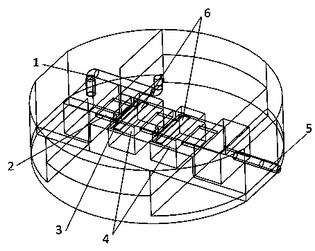
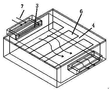
[0018] like Figure 1-2 As shown, a microstrip energy harvester includes a fluid inlet 1, a nozzle 2, a bluff body 3, a microcavity 4, a microstrip 6 and a fluid outlet 5; the fluid inlet 1 is connected to the outside and the nozzle 2 respectively The outlet of the nozzle 2 is connected to the microcavity 4; the bluff body 3 is located at the position corresponding to the outlet of the nozzle 2 inside the microcavity 4 (that is, the bluff body 3 is located in the microcavity 4 At the entrance of the), when the fluid 7 enters the microcavity 4 through the nozzle 2 and interacts with the bluff body 3, the bluff body 3 flutters; One side of the fl...


PUM


Abstract

The invention discloses a micro-strip energy collector, which comprises a fluid inlet, nozzles, flow resistance bodies, miniature cavities, micro-strips and a fluid outlet, wherein the fluid inlet isindependently communicated with the outside and the inlet of each nozzle, and the outlet of each nozzle is communicated with each miniature cavity; the flow resistance bodies are positioned on the positions corresponding to the outlets of the nozzles in the miniature cavities; when fluid enters the miniature cavities through the nozzles and generates a function with the flow resistance bodies, fluttering is generated; the micro-strips are positioned in the miniature cavities, the micro-strips are positioned on one side of a direction where the flow resistance bodies flow along fluid, and keepa set distance with the flow resistance bodies; the fluid outlet is communicated with the inner part and the outer part of each miniature cavity; and the micro-strips are piezoelectric function film materials. By use of the nozzles, the flow rate of the fluid is improved, so that fluid energy collection difficulty is lowered, the flow resistance bodies are added in the inlets of the miniature cavities, so that fluid in the cavities generates vortexes so as to drive the piezoelectric function film materials to generate deformation and generate electric energy.

Description

technical field [0001] The invention relates to the technical field of energy collection, in particular to a microstrip energy collector and a broadband fluid energy collector. Background technique [0002] With the development of science and technology, the improvement of people's living standards and the strong support of the country, the Internet of Things has achieved great development, and has become a research hotspot in universities, research institutions and companies. Among them, the wireless sensor network (WSN) is the key to the Internet of Things, providing material information for the Internet of Things. The sensor nodes of the wireless sensor network have the characteristics of large number and small size, which require small and durable energy supply modules. Theoretically speaking, MEMS micro-energy based on environmental energy harvesting (Energy Harvesting) can provide inexhaustible energy for wireless sensor nodes. Technology generates great interest. ...

Claims


Application Information

Patent Timeline
Patent Type & Authority Applications(China)
IPC IPC(8): H02N2/18
CPCH02N2/185
Inventor 牟笑静周鸿尚正国
Owner 青岛因菲尼思微电子科技有限公司
Why Eureka
Try Eureka