Mechanical ceramic-pulverizing device

A grinding and ceramic technology, applied in grain processing and other directions, can solve the problem of not being able to automatically adjust the torque of mechanical grinding, and achieve the effect of fast rotation speed and increased efficiency

Inactive Publication Date: 2019-03-08
佛山迪骏自动化科技有限公司
View PDF1 Cites 8 Cited by
  • Summary
  • Abstract
  • Description
  • Claims
  • Application Information

AI Technical Summary

Problems solved by technology

[0002] For example, the publication number CN205146327U ceramic mechanical milling device includes a milling chassis and a milling upper plate that cooperates with the milling chassis for milling, wherein the milling chassis includes a first base plate and a number of fixedly mounted on the first base plate. A milling pin, the upper plate for milling includes a second bottom plate and a milling column fixedly installed on the second bottom plate to cooperate with several milling needles for milling, the

Method used


Image

  • Mechanical ceramic-pulverizing device
  • Mechanical ceramic-pulverizing device
  • Mechanical ceramic-pulverizing device

Examples


specific Embodiment approach 1

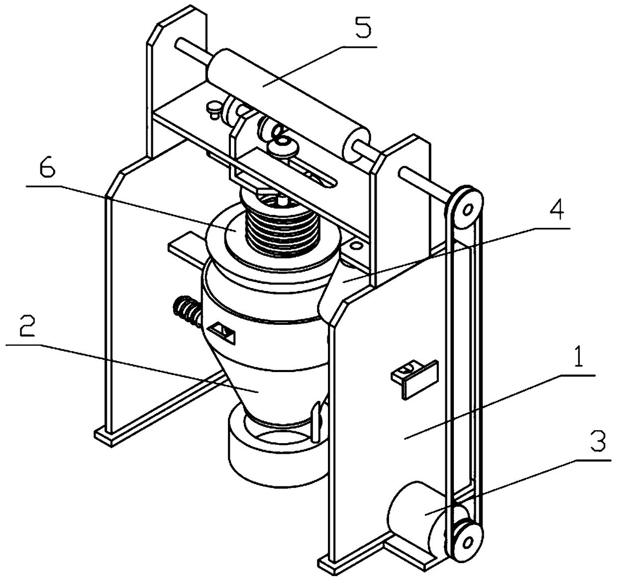
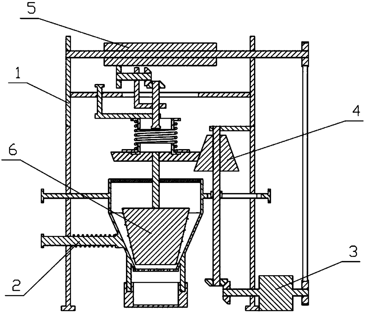
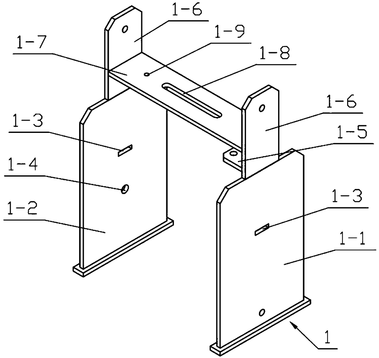
[0031] Combine below Figure 1-10 Describe this embodiment, a ceramic mechanical grinding device, including the whole machine bracket 1, the grinding cylinder 2, the power mechanism 3, the feedback mechanism 4, the transmission mechanism 5 and the grinding mechanism 6, and the feedback mechanism can be driven by the power mechanism 3 at the same time 4 and the transmission mechanism 5 rotate at the same time, and the transmission mechanism 5 pushes the milling mechanism 6 to move downward through the horizontal transmission of the thread, and the compression spring II set on the milling mechanism 6 produces a certain extrusion force on the milling wheel 6-16 , the grinding wheel 6-16 is driven by the conical friction wheel II 6-14 to rotate in the grinding cone 2-2, and the taper of the grinding wheel 6-16 is smaller than the taper of the grinding cone 2-2 , the upper diameter of the milling wheel 6-16 and the milling cone 2-2 is greater than the lower diameter, and the millin...


PUM


Abstract

The invention relates to a mechanical pulverizing device, in particular to a mechanical ceramic-pulverizing device. The device comprises an overall support, a pulverizing barrel, a power mechanism, afeedback mechanism, a transmission mechanism and a pulverizing mechanism. The feedback mechanism and the transmission mechanism can be driven by the power mechanism to rotate simultaneously, the transmission mechanism performs transverse transmission through threads and pushes the pulverizing mechanism to move downwards, a compression spring II arranged on the pulverizing mechanism produces certain extrusion force on a pulverizing wheel, the pulverizing wheel is driven by a cone friction wheel II to rotate in a pulverizing conical barrel, the conical degree of the pulverizing wheel is smallerthan that of the pulverizing conical barrel, the diameters of the upper ends of the pulverizing wheel and the pulverizing conical barrel are greater than those of the lower ends of the pulverizing wheel and the pulverizing conical barrel correspondingly, and after being pulverized by means of the pulverizing wheel, ceramic in the pulverizing conical barrel falls into a storage box through a screening plate.

Description

technical field [0001] The invention relates to a mechanical powder milling device, in particular to a ceramic mechanical powder grinding device. Background technique [0002] For example, the publication number CN205146327U ceramic mechanical milling device includes a milling chassis and a milling upper plate that cooperates with the milling chassis for milling, wherein the milling chassis includes a first base plate and a number of fixedly mounted on the first base plate. A milling pin, the upper plate for milling includes a second bottom plate and a milling column fixedly installed on the second bottom plate to cooperate with several milling needles for milling, the middle part of the first bottom plate is provided with a shaft hole, and the first bottom plate It has a bottom surface and a top surface, and a circular convex rib is protruded from the bottom surface of the periphery of the shaft hole, and several strip-shaped convex ribs are arranged between the circular co...

Claims


Application Information

Patent Timeline
IPC IPC(8): B02C2/10B02C23/16B02C23/00
CPCB02C2/10B02C23/00B02C23/16
Inventor 朱路白杰
Owner 佛山迪骏自动化科技有限公司
Why Eureka
Try Eureka