Independent plate coating drying box device

A self-contained, oven-based technology, applied to the surface coating liquid device, coating, transportation and packaging, etc., can solve the problems of wasting resources, the oven guide wheel does not rotate, etc., to improve efficiency and avoid width narrowing , the effect of reducing loss

Inactive Publication Date: 2019-03-08
QINGYUAN QILI SYNTHETIC LEATHER
View PDF3 Cites 0 Cited by
  • Summary
  • Abstract
  • Description
  • Claims
  • Application Information

AI Technical Summary

Problems solved by technology

[0003] The purpose of the present invention is to provide a stand-alone plate coating oven device to solve the problem of centralized exhaust and drying of the traditional plate coating oven proposed in the above background technology, waste of resources and non-rotation of the inner guide wheel of the oven

Method used


Image

  • Independent plate coating drying box device
  • Independent plate coating drying box device
  • Independent plate coating drying box device

Examples


Embodiment 1

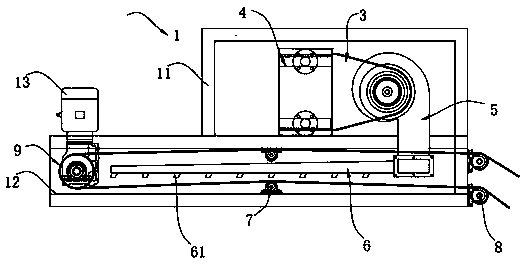
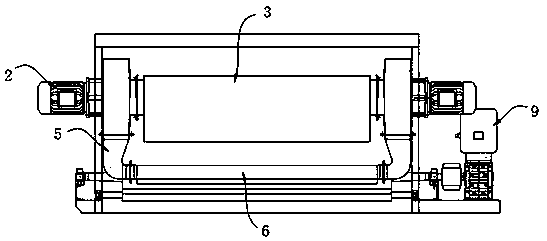
[0022] A free-standing version coating oven device, such as figure 1 and figure 2 As shown, an oven structure 1 is included, and the oven structure 1 includes a cold air box 11 and an oven body 12 installed at the bottom of the cold air box 11, and the cold air box 11 and the oven body 12 are integrally formed, and blowers 2 are installed on both sides of the cold air box 11 , An air collecting hood 3 is installed between the two blowers 2, a heat exchanger 4 is installed on one side of the air collecting hood 3, an air supply pipe 5 is connected to the bottom of the air collecting hood 3, and the air supply pipe 5 is far away from the air collecting hood 3 One end of the air supply row 6 is connected to the bottom surface of the air supply row 6, and a number of uniformly equidistant hot air nozzles 61 are installed on the bottom surface of the air supply row 6. The upper and lower sides of the oven body 12 are symmetrically equipped with conveying guide wheels 7, and one en...

Embodiment 2

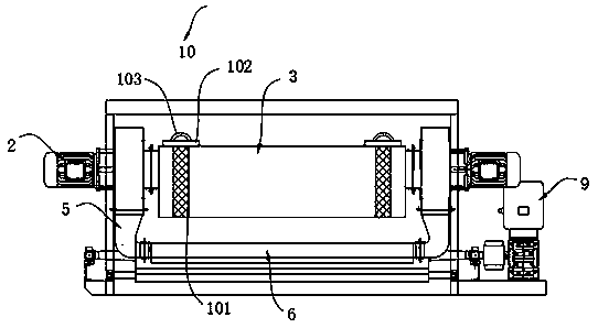
[0028] In order to solve the problem that the impurities in the air are blown into the wind collecting hood 3 during the blowing process and will be adsorbed on the artificial leather during drying, which will affect the quality of the product, the inventor made a design for the wind collecting hood 3 in Example 1. Improvement, as a kind of preferred technical scheme of embodiment 1, such as image 3 As shown, the two ends of the wind collecting hood 3 are symmetrically equipped with filter devices 10, the filter device 10 includes a filter screen plate 101, a limit block 102 is installed on the top of the filter screen plate 101, and a pull ring 103 is installed on the top of the limit block 102 .

[0029] Further, the filter screen plate 101 is plugged on the wind collecting hood 3, and the filter screen plate 101 is plugged and matched with the wind collecting hood 3. When the dust is absorbed too much, the filter screen plate 101 can be extracted, and the filter screen pla...


PUM


Abstract

The invention relates to the technical field of artificial leather production, in particular to an independent plate coating drying box device. The independent plate coating drying box device comprises a drying box structure. A cold air box and the drying box body are of an integrally-formed structure. Air blowers are mounted on the two sides of the cold air box. An air collection hood is mountedbetween the two air blowers. A heat exchanger is mounted on one side of the air collection hood. The bottom of the air collection hood is connected with an air supply pipe. The end, away from the aircollection hood, of the air supply pipe is connected with an air supply row. Multiple hot air spray heads evenly arranged at equal distances are mounted on the bottom face of the air supply row. Conveying guide wheels are symmetrically mounted on the upper side and the lower side in the drying box body. According to the device, the two air blowers are arranged so that the air blowing efficiency can be improved; meanwhile, through the arranged air collection hood and heat exchanger, blown air can be heated and is conveyed into the air supply row through the air supply pipe, and consumption is reduced; and through a corner guide wheel mounted in the drying box body, power is provided through a motor, traction force is provided for operating of artificial leather, and it is guaranteed that artificial leather drying can be carried out constantly.

Description

technical field [0001] The invention relates to the technical field of artificial leather production, in particular to an independent plate coating oven device. Background technique [0002] The manufacturing process of the artificial leather plate coating oven is an important step in the production of artificial leather. The traditional plate coating oven uses heat exchangers to centralize the air supply and exhaust. This kind of device wastes energy and produces a lot of polluting gases and serious pollution. There are hidden dangers in the environment, and the internal guide wheel of the traditional oven has no transmission, and the width of the artificial leather is narrowed due to hard pulling during reverse movement during use. In view of this, we provide a stand-alone plate coating oven device. Contents of the invention [0003] The purpose of the present invention is to provide a stand-alone plate coating oven device to solve the problems of centralized exhaus...

Claims


Application Information

Patent Timeline
Patent Type & Authority Applications(China)
IPC IPC(8): B05D3/04D06N3/00B01D46/12
CPCB01D46/12D06N3/0077B05D3/0413B01D2267/30B01D46/56
Inventor 刘爱明唐伟谢亮何英奇
Owner QINGYUAN QILI SYNTHETIC LEATHER
Why Eureka
Try Eureka