Temporary structure for installation of continuous steel girder bridge and beam segment construction method thereof

A temporary structure and installation technology, applied in the direction of bridges, bridge construction, erection/assembly of bridges, etc., can solve the problems of difficulty in erecting main beams, affecting the lower traffic, high cost, and achieving easy installation and disassembly, cost saving, and easy transportation. Effect

Pending Publication Date: 2019-03-08
浙江中南绿建科技集团有限公司
View PDF0 Cites 5 Cited by
  • Summary
  • Abstract
  • Description
  • Claims
  • Application Information

AI Technical Summary

Problems solved by technology

If a temporary support frame is used for installation, the following problems will be faced: (1) For bridges on land, temporary support frames may affect the lower traffic, and the cost of measures is high; (2) For bridges on water However, due to the complex underwater geological conditions and many uncertain factors, it takes a long period and a high cost to erect a temporary support frame
If a bridge erecting machine is used for erection, the following problems will be faced: (1) the front outrigger of the bridge erecting machine needs to be supported on the previous pier of the beam section to be installed, which makes the bridge erecting machine large in size, large in consumables, and high in transportation costs. Moreover, there are many on-site installation and dismantling procedures, and the installation and dismantling costs are relatively high; (2) The scope of use of the bridge erecting machine is severely restricted by the line shape of the main girder of the bridge. control

Method used


Image

  • Temporary structure for installation of continuous steel girder bridge and beam segment construction method thereof
  • Temporary structure for installation of continuous steel girder bridge and beam segment construction method thereof
  • Temporary structure for installation of continuous steel girder bridge and beam segment construction method thereof

Examples


Embodiment Construction

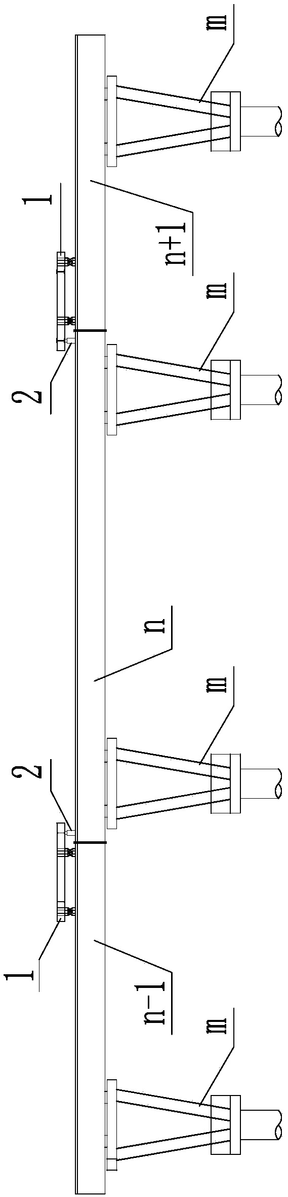
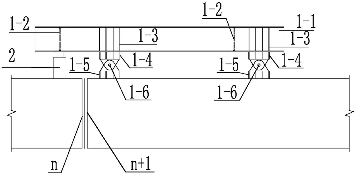
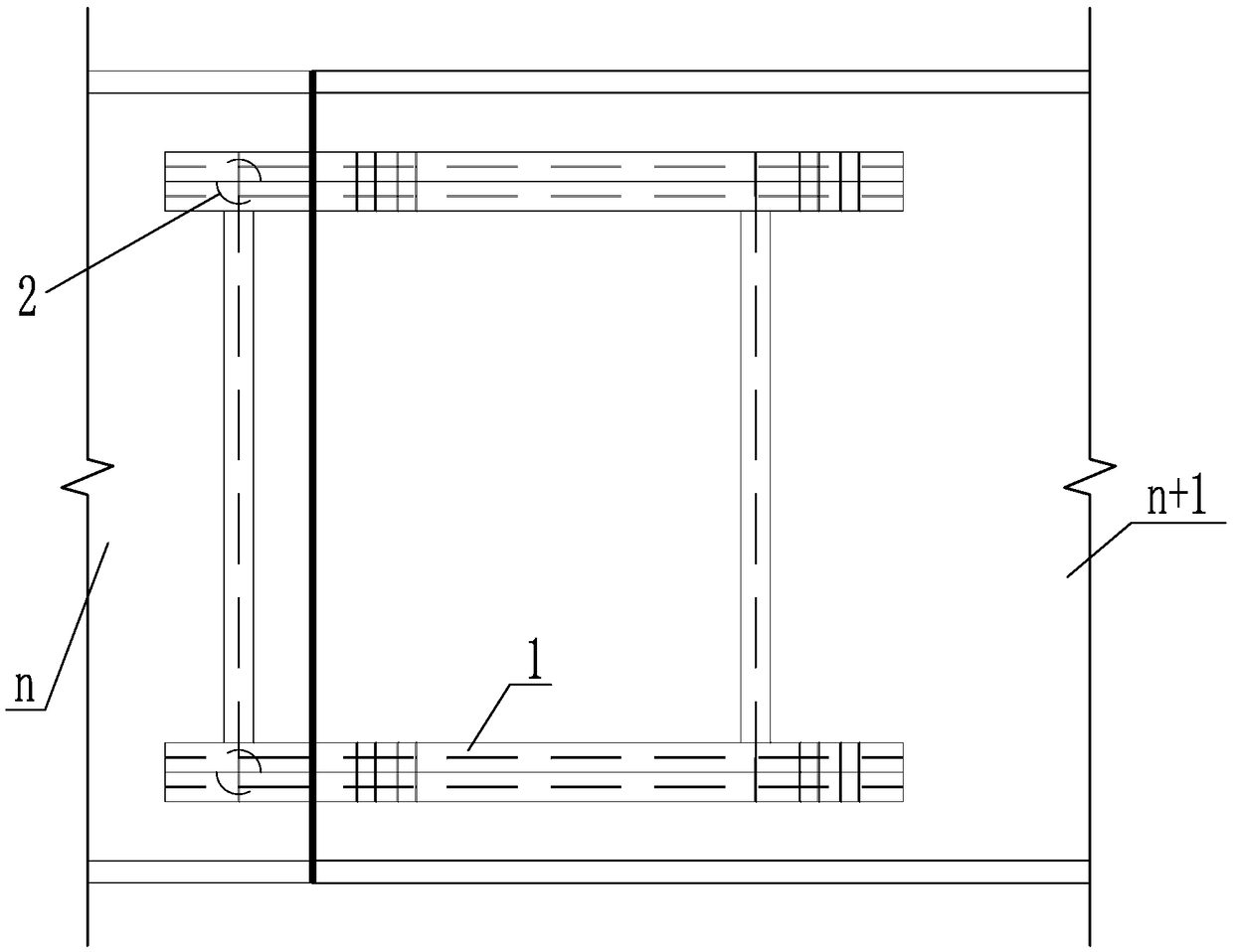
[0067] Such as Figure 1 to Figure 18 As shown, it is a temporary structure for installation of a continuous steel girder bridge in the present invention, including a hanger 1 and a displacement adjustment device 2, and the hanger 1 acts on the displacement adjustment device 2.

[0068] The displacement adjustment device 2 includes a single vertical jack 2-1, three horizontal jacks 2-2, a reaction force seat 2-3, a limit groove 2-5 and a bridge top steel backing plate 2-8. Two transverse jacks 2-2 arranged symmetrically to each other are arranged along the X-axis direction of the installed beam section, and a single transverse jack 2-2 is arranged along the Y-axis direction of the installed beam section. The force base 2-3 is welded and fixed; the vertical jack 2-1 is set along the Z-axis direction of the installed beam section, and the vertical jack 2-1 is set in the limiting groove 2-5. The bottom surface of the limiting groove 2-5 is welded with the steel backing plate 2-6...


PUM


Abstract

The invention discloses a temporary structure for installation of a continuous steel girder bridge and a beam segment construction method thereof. The structure comprises a pylon and a displacement adjusting device, the pylon comprises a pylon main beam, a pylon beam, a pylon main beam stiffening plate, a pylon main beam ear, a bridge top surface ear and a pin shaft, the pin shaft is connected between the pylon main beam ear and the bridge top surface ear, and the displacement adjusting device comprises a vertical jack, a horizontal jack, a counter-force seat, a limit groove and a bridge top surface steel plate. The method comprises the steps of a, the design of the temporary structure; b, the production of a rack; c, the production of the displacement adjusting device; d, the continuous construction of the beam segment. The structure has the advantages of small consumables, simple installation and disassembly, cost saving and short construction period, is not limited by the line typeof the main beam of the bridge, and can well control the positioning accuracy of the main beam of the pylon; the steel beams are not limited by construction conditions during segmentation, and a segmentation line is set at the zero bending moment according to the force condition, thereby reducing the internal stress of the position weld of the segmentation line and indirectly increasing the connection strength of the two sections of the steel beams.

Description

technical field [0001] The invention belongs to the technical field of continuous steel girder bridge construction, and in particular relates to a temporary structure for continuous steel girder bridge installation and a construction method for the girder section thereof. Background technique [0002] With the increase of China's steel production and the development of steel structure processing and manufacturing technology, the number of steel bridges being built is constantly increasing. Especially in viaducts on municipal roads, steel box girders are favored and concerned by more and more bridge engineers because of their good torsional performance, fast construction speed, and reduced impact on traffic during construction. [0003] Compared with simply supported beams, under the action of constant live load, the negative bending moment generated by the fulcrum of the continuous beam bridge has an unloading effect on the positive bending moment at the mid-span, so that th...

Claims


Application Information

Patent Timeline
Patent Type & Authority Applications(China)
IPC IPC(8): E01D21/00
CPCE01D21/00
Inventor 蒋永扬郑永林张林春唐国财倪挺韩佳妮
Owner 浙江中南绿建科技集团有限公司
Why Eureka
Try Eureka