Pneumatic diving pump and use method thereof

A technology for pneumatic submersible pumps and water pumps, which is applied to pumps, pump devices, non-variable-capacity pumps, etc., can solve the problems of insufficiently optimized fan blade structure design, low aerodynamic efficiency, and short service life, etc. The effect of convenient assembly, high work efficiency and strong sewage discharge capacity

Pending Publication Date: 2019-03-08
台州开浪泵业股份有限公司
View PDF0 Cites 0 Cited by
  • Summary
  • Abstract
  • Description
  • Claims
  • Application Information

AI Technical Summary

Problems solved by technology

However, for the existing pneumatic submersible pump structure, due to the insufficient optimization of the cylinder and fan blade structure design, it is easy to cause blade wear, and the aerodynamic efficiency is not high, and the service life is not long

Method used


Image

  • Pneumatic diving pump and use method thereof
  • Pneumatic diving pump and use method thereof
  • Pneumatic diving pump and use method thereof

Examples


Embodiment

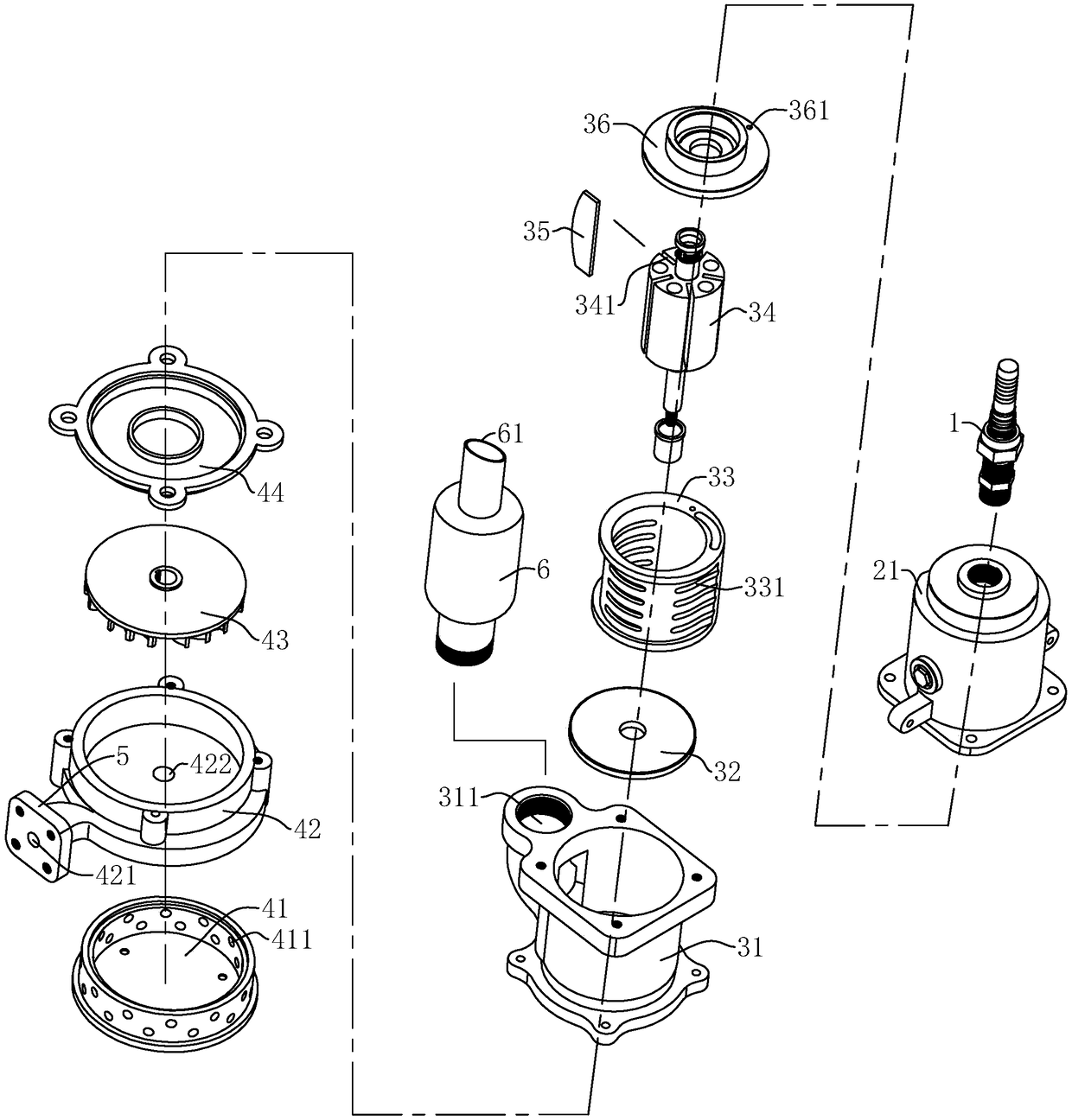
[0038] A kind of pneumatic submersible pump, refer to figure 1 and figure 2 As shown, it includes an air pipe joint 1 for connecting to an external air source, a lubricator 2 connected to the air pipe joint 1, connected under the lubricator 2 to receive the air source and atomized oil, and used to convert the air source to rotation A powered air motor 3, a water pump body 4 connected to the power output end of the air motor 3 and having a water inlet 422, a drain connector 5 connected to the output end of the water pump body 4, and a muffler 6 connected to the exhaust port 311 of the air motor 3. For the external air source, it can be generated by an air pump or an air source generator.

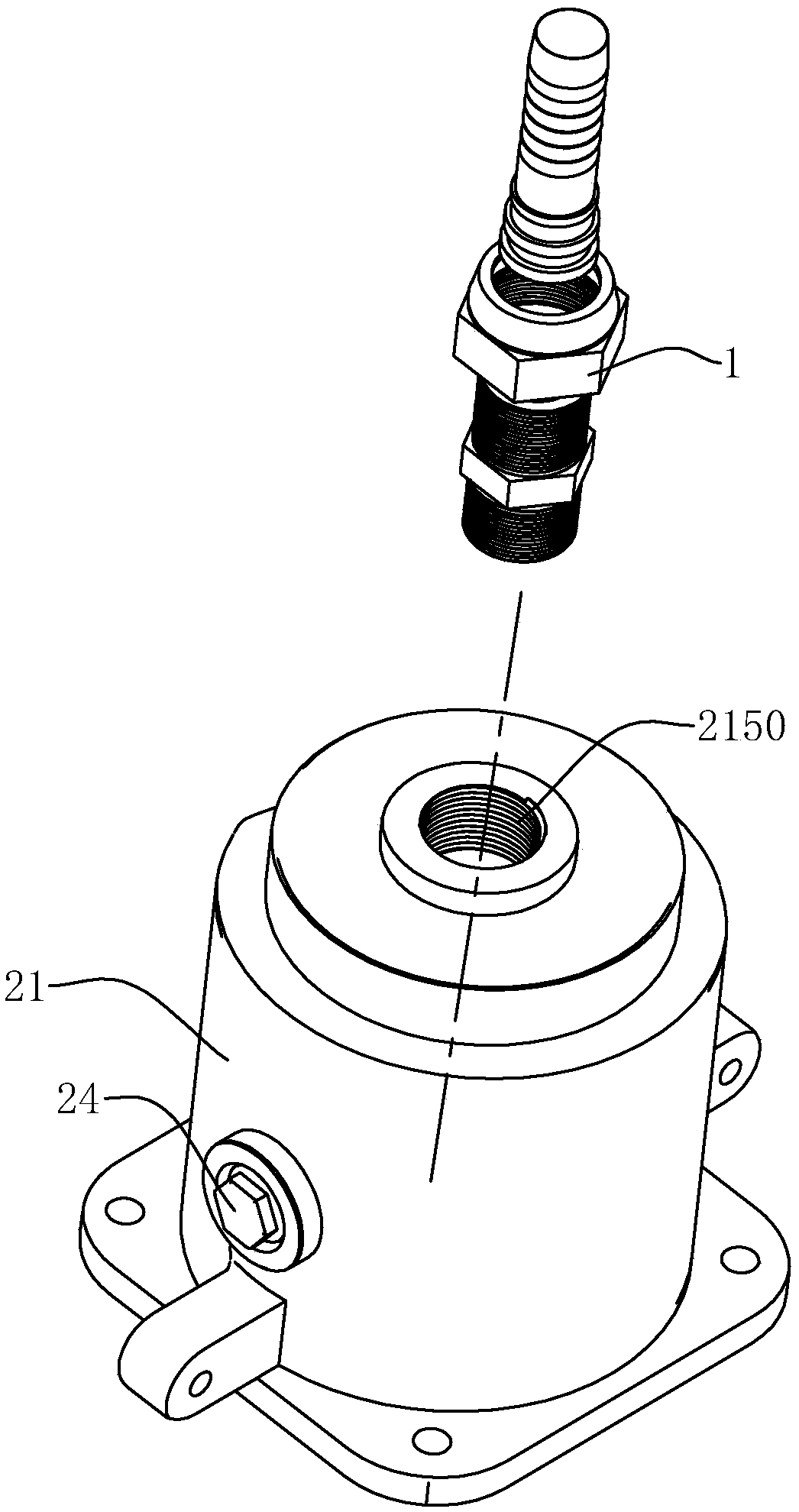
[0039] For lubricator 2, you can continue to refer to image 3 , Figure 4 as well as Figure 5 As shown, the lubricator 2 includes a first cylinder 21 with a first inner cavity 211 and an oil storage chamber 212, a first air valve 22 disposed on the oil storage chamber 212 facing the dire...


PUM


Abstract

The invention discloses a pneumatic diving pump and a using method thereof, belongs to the field of diving pumps and solves the problems of service life and reliability. The key points of the technical scheme comprise that a lubricator comprises a first cylinder body, a first air valve, a second air valve, and an oil injection port, wherein the first cylinder body is provided with a first inner cavity and an oil storage cavity, the first air valve is arranged on the oil storage cavity and faces towards an air pipe joint, the second air valve is arranged below the oil storage cavity and faces apneumatic motor and the oil injection port is located on the first cylinder body and is communicated with the oil storage cavity. The first inner cavity is communicated with the air pipe joint, and when the gas source pressure does not reach a set value, the oil storage cavity is in a closed state; and when the gas source pressure reaches the set value, oil liquid in the oil storage cavity is atomized and sprayed out, so that effects of prolong the service life and enhancing power are achieved.

Description

technical field [0001] The invention relates to the field of submersible pumps, in particular to a pneumatic submersible pump. Background technique [0002] Pneumatic submersible pump power machines use compressed air as the medium, and the gauge pressure is 0.3mpa ~ 0.7mpa. Compressed air enters the cylinder or turbine after expansion and work (because the gas cannot be fully expanded, there is still a certain pressure in the exhaust chamber. ), it is discharged to the atmosphere at a certain pressure and flow rate, thus generating energy and a lot of exhaust noise. Some scholars have studied that the residual pressure of the vane type is about 0.3-0.35mpa, while the turbine type and gear type wind motor have a greater residual pressure. [0003] For the application of existing sewage submersible pumps, electric submersible pumps are driven by motors and operate underwater, so efficient sealing is required to avoid hidden dangers of electric leakage. Therefore, the use of...

Claims


Application Information

Patent Timeline
Patent Type & Authority Applications(China)
IPC IPC(8): F04D13/04F01C13/04F01C1/344F01C21/00F01C21/04F01C20/00
CPCF04D13/04F01C1/344F01C13/04F01C20/00F01C21/00F01C21/04
Inventor 杨世富马美良
Owner 台州开浪泵业股份有限公司
Why Eureka
Try Eureka