multi-hole fluid connector

A connector and fluid technology, applied in the direction of sealing surface connection, pipe/pipe joint/pipe fitting, through components, etc., can solve the problems of high cost, bulky, complex structure, etc., achieve light weight, small volume, locking method simple effect

Active Publication Date: 2020-11-03
万硕(成都)航空科技有限公司
View PDF3 Cites 0 Cited by
  • Summary
  • Abstract
  • Description
  • Claims
  • Application Information

AI Technical Summary

Problems solved by technology

[0004] The technical problem to be solved by the present invention is that the current joints are complex in structure, bulky and high in cost when multi-point connections are made. The purpose is to provide a multi-hole fluid connector, which not only has a simple structure and locking method, is convenient for rapid testing and use, and is small in size , light weight, easy to operate

Method used


Image

  • multi-hole fluid connector
  • multi-hole fluid connector
  • multi-hole fluid connector

Examples


Embodiment 1

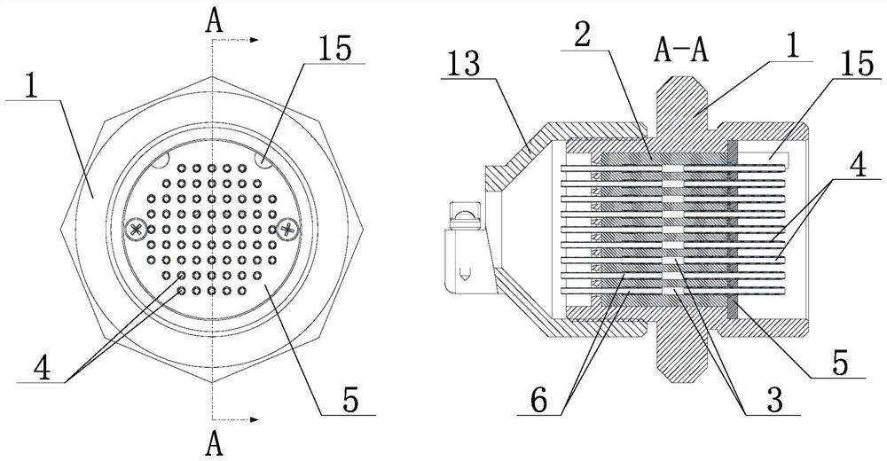
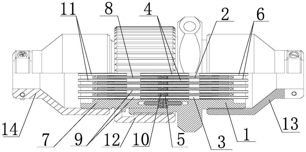
[0029] Such as figure 1 , figure 2 and image 3 As shown, the porous fluid connector of the present invention includes a male end connector and a female end connector, and is characterized in that the male end connector includes a porous connection male end housing 1, and the porous connection male end housing 1 is sleeved There is a public-end porous sealing body 2, and a plurality of public-end dense channels 3 arranged in parallel and running through both ends of the male-end porous sealing body 2 are arranged in the male-end porous sealing body 2, and one end of the male-end porous sealing body 2 is provided with a male end The porous baffle 5, the male-end porous baffle 5 is provided with installation and positioning step holes corresponding to the male-end intensive channels 3 one-to-one, and the end of the male-end dense channel 3 where the male-end porous baffle 5 is located is inserted with a connecting pin 4 , the other end is inserted with a male end capillary co...

Embodiment 2

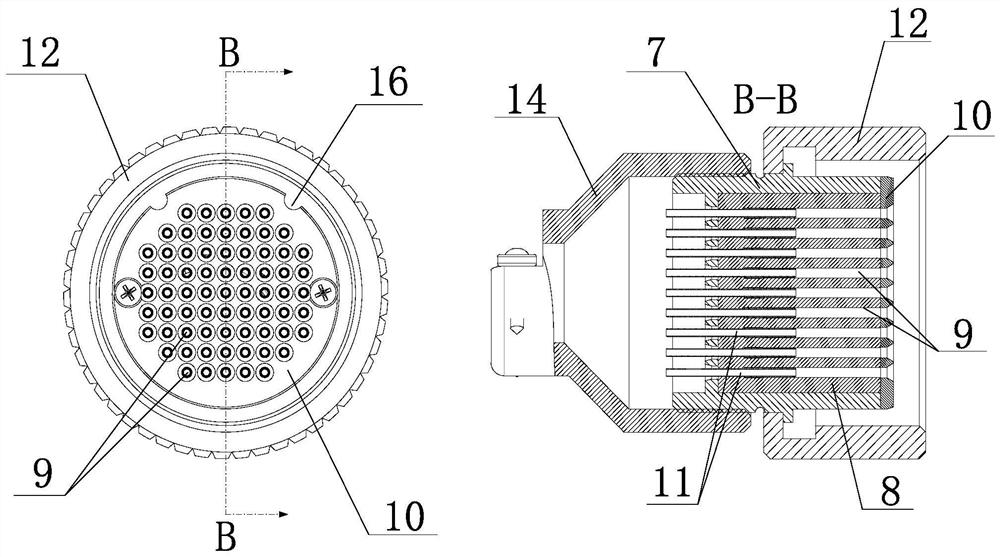
[0032] Such as figure 2 As shown, the porous fluid connector of the present invention, on the basis of Embodiment 1, is provided with an external thread on the outer wall of the porous connection male end housing, and a connecting nut 12 is provided on the outer movable sleeve of the porous connecting female end housing, and the inner wall of the connecting nut The thread cooperates with the external thread of the outer wall of the porous connection male end housing. When the male end connector and the female end connector are mated and connected, the connection lock is formed by tightening the connection nut and the external thread of the porous connection male end housing.

[0033] Preferably, the end where the male end capillary connection pin on the porous connection male end housing is connected to the male end wire harness 13, and the end where the female end capillary tube connection needle on the porous connection female end housing is connected to the female end wire ...


PUM


Abstract

The invention discloses a porous fluid connector. The porous fluid connector comprises a male end connector and a female end connector. The male end connector comprises a porous connection male end shell, a male end porous sealing body is arranged in the porous connection male end shell in a sleeved mode, the male end porous sealing body is internally provided with a plurality of male end dense pore channels. A male end porous baffle is arranged at one end of the male end porous sealing body, connecting pins are arranged at the ends, at which the male end porous baffle is located, of the maleend dense hole channels in an inserting mode, and male end capillary connecting pins are arranged at the other ends of the male end dense pore channels in an inserting mode. The female end connector includes a porous connection female end shell, a female end porous sealing body is arranged in the porous connection female end shell in a sleeved mode, and the female end porous sealing body is internally provided with a plurality of female end dense pore channels. A female end porous baffle is arranged at one end of the female end porous sealing body, and female end capillary connecting pins arearranged at the other end of the female end porous sealing body in an inserting mode. The porous fluid connector is simple in structure and locking mode, convenient to use for rapid testing, small insize, light in weight and convenient to operate.

Description

technical field [0001] The invention relates to a connector, in particular to a multi-hole fluid connector. Background technique [0002] Usually, engine testing involves gas pressure testing at many points, including aeroengines, gas turbines, automobile engine tests, wind tunnel tests, etc. Considering the applicability and technical aspects, people generally lead the pressure points to be tested to the outside through the pressure induction pipe in the early stage of test preparation, and then connect the pipes to the test system through welded joints. When an engine is tested, all the work needs to be done again, one by one manual connection and disassembly, resulting in low efficiency, high failure rate, and heavy workload of the staff. [0003] At present, most of the joints are single-point connections. For example, joints with application number 201510937479.6 and application number 201720597969.0 can be connected at multiple points. They use a sealing ring for each...

Claims


Application Information

Patent Timeline
Patent Type & Authority Patents(China)
IPC IPC(8): F16L19/025F16L19/03
CPCF16L19/0212
Inventor 张彬吴倩
Owner 万硕(成都)航空科技有限公司
Why Eureka
Try Eureka