
Drainage pipeline pocket-shaped water plugging device and construction installation structure and water plugging and unplugging method

A technology for drainage pipes and installation structures, which is applied to pipe components, pipes/pipe joints/fittings, mechanical equipment, etc., can solve problems such as difficulty, high cost, and large use limitations, and achieves fast blocking time, convenient use, easy-to-get effects

Pending Publication Date: 2019-03-08
BEIJING MUNICIPAL ENG RES INST +2
View PDF1 Cites 0 Cited by
  • Summary
  • Abstract
  • Description
  • Claims
  • Application Information

AI Technical Summary

Problems solved by technology

[0005] In order to overcome the defects and deficiencies of the above-mentioned technologies, the present invention provides a pocket-shaped water blocking device for drainage pipes, a construction and installation structure, and a water blocking and dismantling method. Both have huge volume and mass, large use limitations, long time, high cost, and technical problems that are greatly affected by water flow velocity and water level during construction.

Method used


Image

  • Drainage pipeline pocket-shaped water plugging device and construction installation structure and water plugging and unplugging method
  • Drainage pipeline pocket-shaped water plugging device and construction installation structure and water plugging and unplugging method
  • Drainage pipeline pocket-shaped water plugging device and construction installation structure and water plugging and unplugging method

Examples


Embodiment Construction

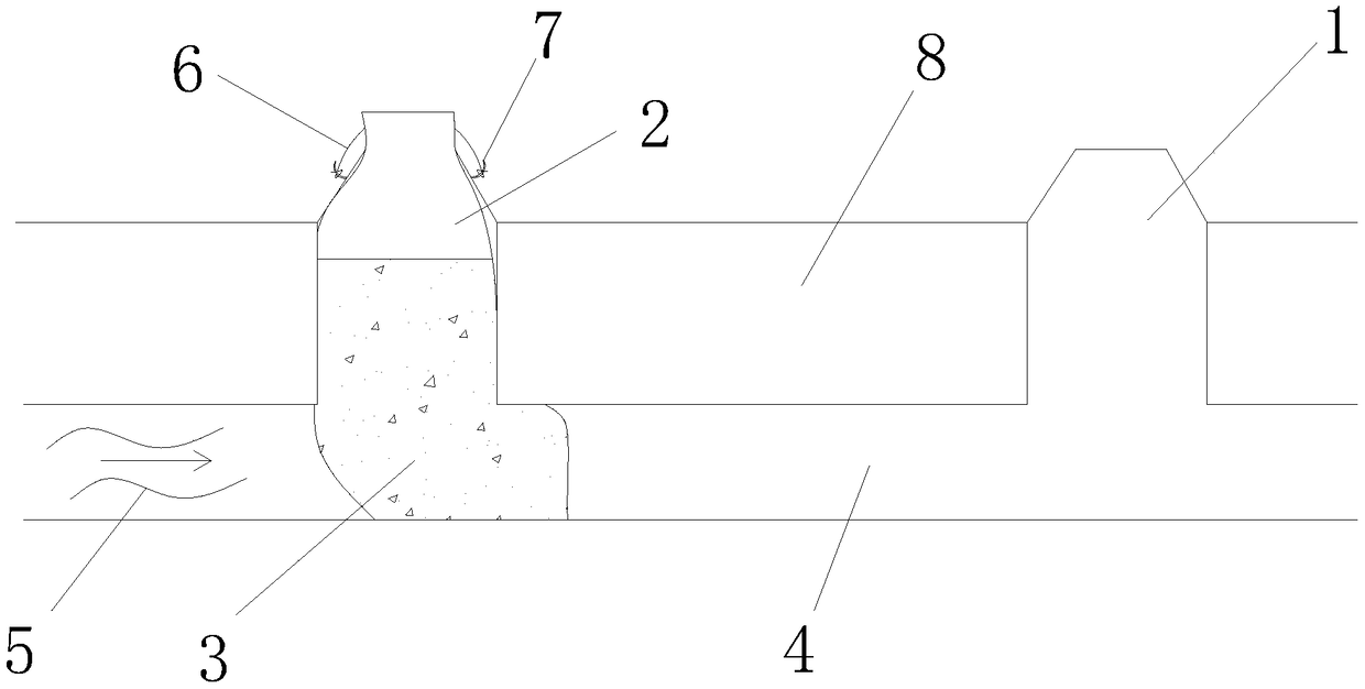
[0027] The specific embodiments of the present invention will be further described below in conjunction with the accompanying drawings.

[0028] The following examples are only examples for clearly illustrating the present invention, rather than limiting the implementation of the present invention. For those of ordinary skill in the art, on the basis of the following descriptions, other different forms of changes or changes can also be made, and these obvious changes or changes that belong to the spirit of the present invention are still within the protection scope of the present invention middle.

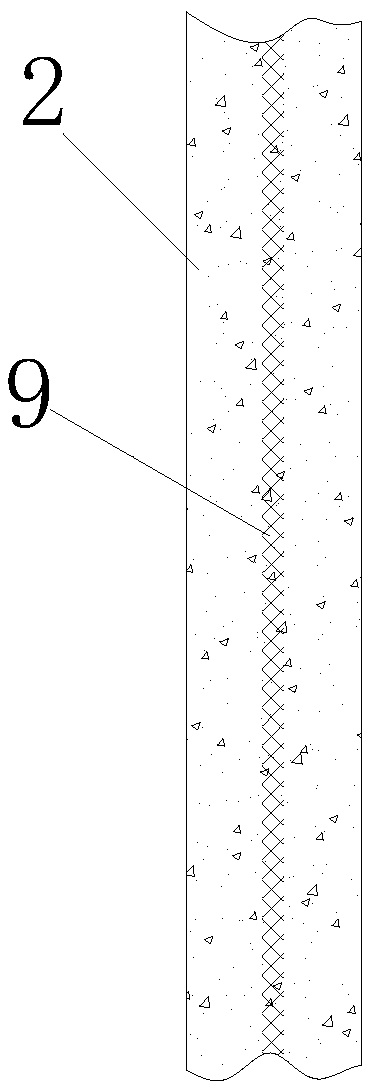
[0029] Referring to each figure, the drainage pipe pocket-shaped water blocking device includes an open pocket 2, and the pocket 2 is made of at least two layers of flexible materials.

[0030] see figure 2 , 3 , the pocket 2 is formed by hot-melt compounding of three layers of materials, the flexible material of the inner layer and the outer layer and the steel mesh reinforcem...


PUM


Abstract

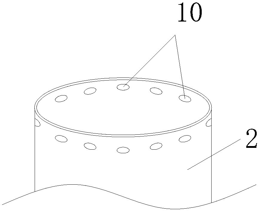
The invention discloses a drainage pipeline pocket-shaped water plugging device. The drainage pipeline pocket-shaped water plugging device comprises a pocket with an upper opening. According to a construction installation structure of the water plugging device, a plurality of vertical shafts communicated with each other are arranged above a drainage pipeline which is transversely arranged, the pocket is arranged in the vertical shafts, and a steel wire rope penetrates through rope holes in the opening to be fixed at the shaft openings of the vertical shafts, filling materials fill the pocket from the opening, and the vertical shafts and the drainage pipeline at the bottoms of the vertical shafts are sealed and blocked until the bottom of the pocket filled with the filling materials expandsoutwards. A water plugging and unplugging method of the water plugging device comprises the following steps that 1) the pocket is put, wherein the pocket is put from the vertical shafts, and the bottom of the pocket makes full contact with the drainage pipeline which is transversely arranged; 2) the opening of the pocket is fixed at the shaft openings; 3) the materials are poured, the filling materials are poured into the pocket from the opening of the pocket, so that the bottom of the pocket is expanded to the periphery and is diffused until the drainage pipeline is completely closed; and 4)operation and unplugging are carried out, wherein the filling materials are taken out after the operation is completed, and then the pocket is taken out. According to the drainage pipeline pocket-shaped water plugging device, the technical problems that an existing air bag water plugging device is prone to being cracked, water leakage easily occurs in the case of plugging through a steel plate, and dismounting of the steel plate is difficult can be solved.

Description

technical field [0001] The invention relates to the field of plugging devices for water supply and drainage pipes, in particular to a pocket-shaped water blocking device for drainage pipes, a construction and installation structure, and a water blocking and removing method. Background technique [0002] At present, there are generally two methods for water blocking of drainage pipes, one is to block with air bags, and the air is released during removal. Its disadvantages are as follows: 1) the safety is not high, due to reasons such as rubber fatigue, excessive air pressure and sharp objects, the airbag will easily explode and hurt people; 2) the installation is inconvenient. It requires multiple people to coordinate and carry it together, or a crane is needed to put the air bag into the underground pipeline; 3) The use is limited. When there is silt or solid waste in the pipeline, the airbag cannot be installed, and the cross section of the pipeline is square or other non-c...

Claims


Application Information

Patent Timeline
IPC IPC(8): F16L55/105
CPCF16L55/105
Inventor 王光明司金艳王灏吴鹏鹏刘瑄
Owner BEIJING MUNICIPAL ENG RES INST
Learn More