Channeling-free deep hole blasting shaft forming process

A technology of groove depth and craftsmanship, applied in blasting, earth-moving drilling, underground transportation, etc., can solve the problems of difficult discharge of blasting smoke, difficulty in blasting, and large amount of dredging works, so as to reduce the probability of hole plugging and reduce the number of holes. Effect

Pending Publication Date: 2019-03-08
远安县燎原矿业有限责任公司
View PDF4 Cites 9 Cited by
  • Summary
  • Abstract
  • Description
  • Claims
  • Application Information

AI Technical Summary

Problems solved by technology

However, there are also many disadvantages, such as the need for too many eyelets, the high quality requirements for the eyeholes, and the deflection rate of the eyelets must not exceed the specified value, otherwise the holes need to be refilled; During blasting, due to the unreasonable charge structure and insufficient cutting compensation space during blasting, hole blocking is likely to occur. Once hole blocking occurs, the amount of dredging work will be large, which will seriously affect the progress of the project; the gun smoke produced by the third layered blasting is difficult Fourth, in some areas where the geological structure is developed, there are large cracks, faults, etc. in the rock body and the lithology is relatively soft. large displacement of the fracture surface
If the delay time of the two adjacent holes is long, the rear row of column charges will be broken before the detonator is detonated, which will interrupt the local charge transmission, which will bring great difficulties to the subsequent blasting.

Method used


Image

  • Channeling-free deep hole blasting shaft forming process
  • Channeling-free deep hole blasting shaft forming process

Examples


Embodiment 1

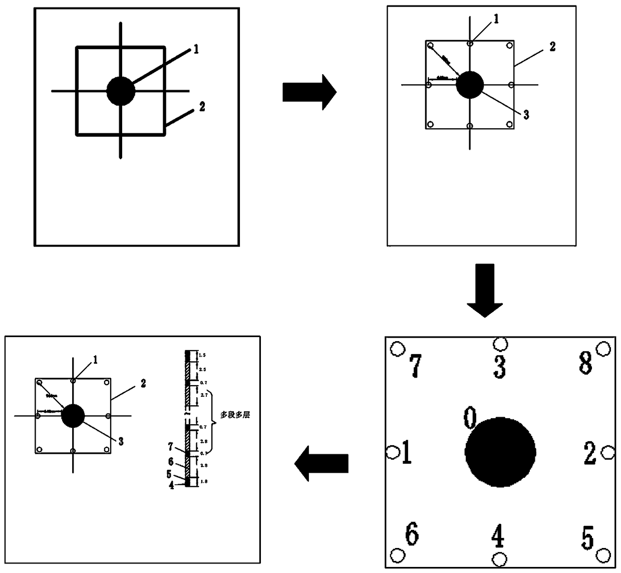
[0024] Aiming at the importance of the shaft in the roadway project of Yichang Phosphate Mine and the characteristics of low safety, poor working environment, slow dissipation of the blast hole and poor ventilation in the construction process of the high shaft with the common method. Combining the advantages of the deep hole blasting and cutting method of the high-speed shaft, it is further optimized in reducing the number of holes, reducing the blockage of the blast hole and the difficulty of ventilation, so as to ensure the safety and high efficiency of the first-time well completion.

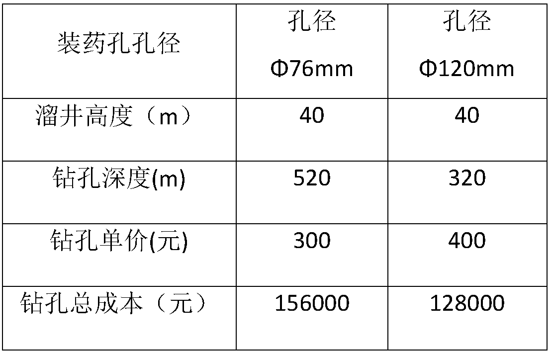
[0025] Drill one Φ600 hollow hole along the center of the section, and drill 8 Φ120 charging holes at equal intervals along the periphery of the section (76mm charging holes can also be used, but the cost is higher and give up), and the half-second delay detonation tube is adopted. Delayed blasting.

[0026]

[0027] All drilling holes must be parallel and the deflection rate shall not exc...


PUM


Abstract

The invention provides a channeling-free deep hole blasting shaft forming process. The process comprises the following steps that the hole pitch L between charging holes and a hollow hole is adjustedand controlled to be 2-3 m according to the formula of L=pi (D<2>+d<2>) (k+1) / [4(D+d)(k-1)]; according to the adjustment and control of the diameter of the charging hole, the number N of the explosive charging blast holes is calculated by utilizing the formula of N=msq / r eta; and the nine holes are formed in the cross section of a cutting shaft, the hollow hole in the middle is not charged with explosives, the number of the charging holes is eight, the eight charging holes are uniformly distributed on the periphery of the hollow hole, each charging layer comprises an explosive section and a fine slag section, and then shaft forming is completed. By adopting the technical scheme, the phi 600 large hollow hole is drilled in the center line of a drop shaft, the sufficient free surface and acompensation space are provided for full drop shaft blasting at one time, and follow-up channeling-free tunneling is realized; the blast smoke after blasting is discharged more quickly through the phi600 large hollow hole, so that the retention time of poisonous and harmful gas on the working surface is reduced, and the ventilation difficulty is reduced; and only eight phi 120 charging holes aredrilled in the whole section, segmented time-delay blasting is carried out, compared with the process of drilling small phi 76 holes as the charging holes, the drilling work amount is reduced by 38%,and the tunneling speed is improved by 30% compared with the original speed.

Description

technical field [0001] The invention relates to a high chute forming process, in particular to a chute transportation system developed outside the vein, and a well forming process for mining mines with high chute height and a large number. Background technique [0002] The Shimen chute transportation system is adopted, and the height of the chute varies from 10 to 90 meters. For the construction of high chute, the safety of the common method is too low, the ventilation is difficult, the environment is poor, and the construction is difficult. However, in practice, there are often unqualified hole quality, unreasonable charge structure or insufficient plugging of the blast hole, and when the blast hole encounters a structural zone, it will cause hole plugging or well completion failure. Therefore, under the background of the existing technology, the research adopts the technology of deep hole blasting without cutting in the high chute. [0003] The construction of high chute ...

Claims


Application Information

Patent Timeline
Patent Type & Authority Applications(China)
IPC IPC(8): F42D1/00F42D3/04E21F13/00
CPCE21F13/00F42D1/00F42D3/04
Inventor 吴保才姚会熊杰瞿定军邹珊珊
Owner 远安县燎原矿业有限责任公司
Why Eureka
Try Eureka