Rapid lens size detection jig
A technology for detecting fixtures and dimensions, which is applied in the field of optical inspection, and can solve problems such as material waste, damaged lenses, and unusable lenses
- Summary
- Abstract
- Description
- Claims
- Application Information
AI Technical Summary
Problems solved by technology
Method used
Image
Examples
Embodiment 1
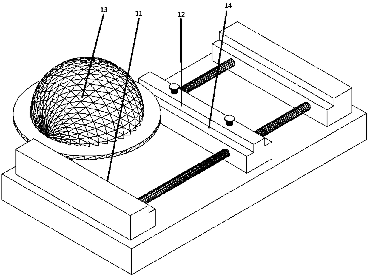
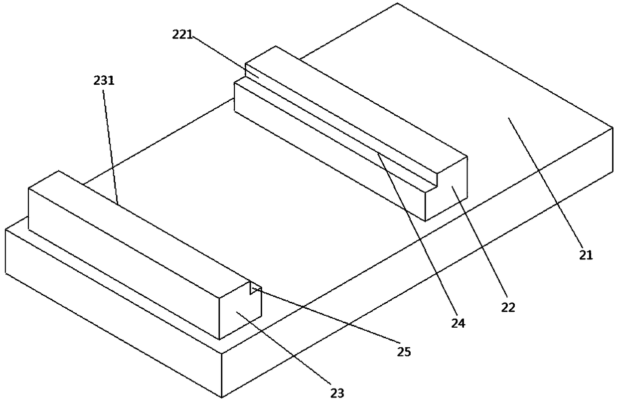
[0026] refer to figure 2 As shown, a lens size rapid detection jig includes a base 21, on which a detection platform is arranged, and the detection platform includes a first detection head 23 and a The second detection head 22. Specifically, the first detection head 23 is parallel to the second detection head 22 and has the same structural size. What is important is that the length of the first detection head 23 and the second detection head 22 is greater than the design diameter of the lens to be detected; the first detection head 23 The inner side of the upper end surface is provided with a first locking groove 25, and the inner side of the upper end surface of the second detection head 22 is provided with a second locking groove 24 corresponding to the position of the first locking groove 25 and having the same structure. The height of the second clamping groove 24 is equal to the edge design thickness of the lens to be detected, and the distance between the first detecti...
Embodiment 2
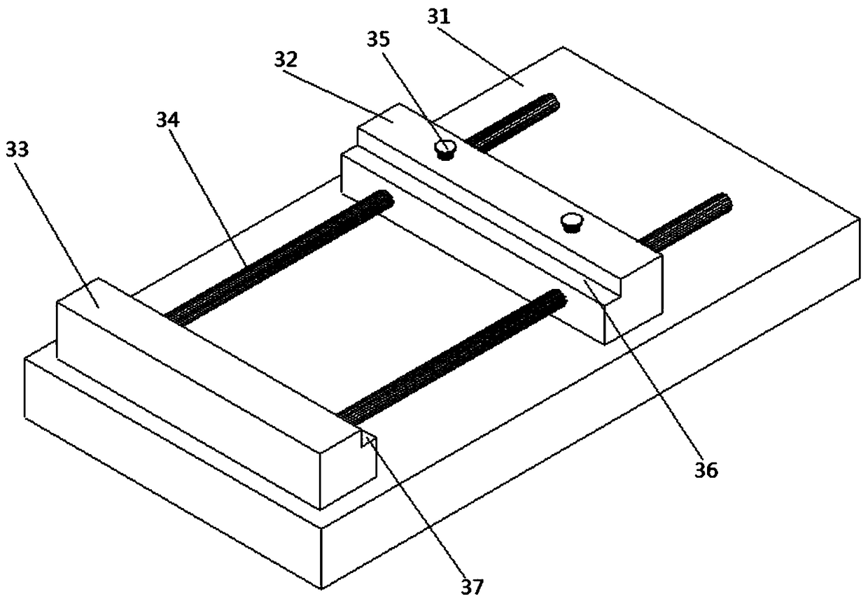
[0028] refer to image 3 As shown, a lens size rapid detection jig includes a base 31, and a detection platform is arranged on the base 31. The detection platform includes a first detection head 33 and a second detection head 33 which are arranged parallel to each other above the base 31 and have the same structural size. The detection head 32 and the second detection head 32 are connected to the first detection head 33 through a guide shaft 34 . Specifically, the upper surface of the first detection head 33 arranged on one end of the base is fixedly connected with the base 31, which can be riveted or welded; the guide shaft 34 is perpendicular to the first detection head 33 and one end thereof is connected to the first detection head 33 Fixedly connected, the second detection head 32 runs through the guide shaft 34 and is movably connected with the guide shaft. Specifically, the relative position of the second detection head 32 and the first detection head 33 can be determine...
Embodiment 3
[0032] refer to Figure 5As shown, a lens size rapid detection jig includes a base 51 on which a detection platform is arranged, and the detection platform includes two ends parallel to the upper surface of the base and fixedly connected with the base. The first detection head 52 and the second detection head 53 also include a guide shaft 55 and a third detection head 54, one end of the guide shaft 55 is fixedly connected to the first detection head 52, and the other end is fixedly connected to the second detection head 43, so The second detection head 52 has the same structural size as the first detection head 53, the third detection head 54 is arranged between the first detection head 52 and the second detection head 53, and the guide shaft 55 runs through the third detection head 54 and the second detection head 53. The third detection head 54 can be flexibly connected, the top of the third detection head 54 is provided with a positioning knob 56; The second locking slot 5...
PUM
 Abstract
Description
Claims
Application Information
 - R&D
- Intellectual Property
- Life Sciences
- Materials
- Tech Scout
- Unparalleled Data Quality
- Higher Quality Content
- 60% Fewer Hallucinations
Browse by: Latest US Patents, China's latest patents, Technical Efficacy Thesaurus, Application Domain, Technology Topic, Popular Technical Reports.
© 2025 PatSnap. All rights reserved.Legal|Privacy policy|Modern Slavery Act Transparency Statement|Sitemap|About US| Contact US: help@patsnap.com


