Optical detector for medical bone nail

An optical detection and bone nail technology, which is applied in the direction of using optical devices, measuring devices, instruments, etc., can solve the problems of inability to evaluate from multiple angles, low measurement accuracy, and bone screw tilt, and achieve stable and reliable measurement data, high detection efficiency, The effect of small axis runout

Pending Publication Date: 2019-03-08
XIAMEN YINGHAODA PRECISION EQUIP CO LTD
View PDF0 Cites 2 Cited by
  • Summary
  • Abstract
  • Description
  • Claims
  • Application Information

AI Technical Summary

Problems solved by technology

Traditional bone nail measurement usually uses calipers or optical image detection equipment. Although caliper measurement is easy to operate, the biggest disadvantage is that the measurement accuracy is low and the operation errors of different personnel are large; when measuring on optical image detection equipment, Because the bone nail cap is larger than the nail body, placing the bone screw on the measurement platform will cause the bone screw to tilt, and the level cannot be guaranteed, which will directly affect the measurement results. In addition, due to the wear and tear of the processing machine tool, some parts of the bone screw may It will be asymmetrical, and usually the optical detection equipment can only observe the general situation of the fixation angle of the bone screw, and cannot evaluate from multiple angles

Method used


Image

  • Optical detector for medical bone nail
  • Optical detector for medical bone nail
  • Optical detector for medical bone nail

Examples


Embodiment

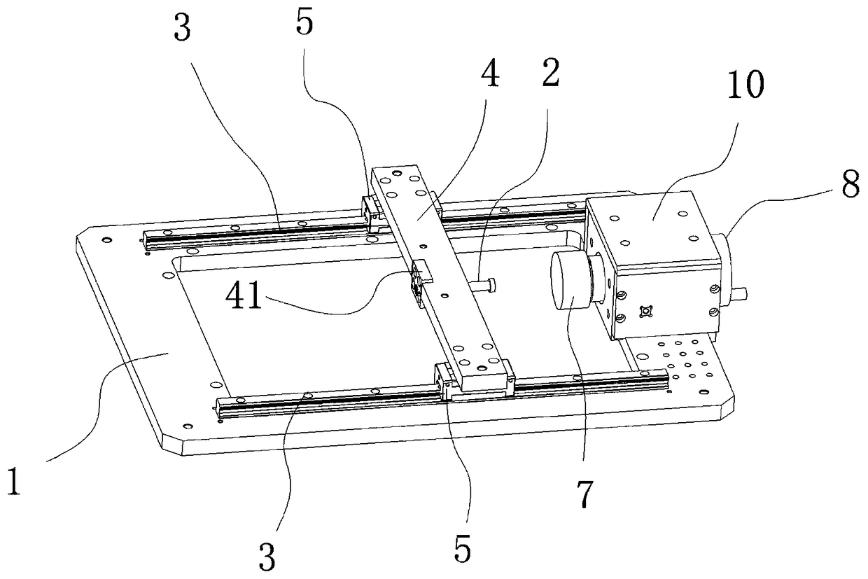
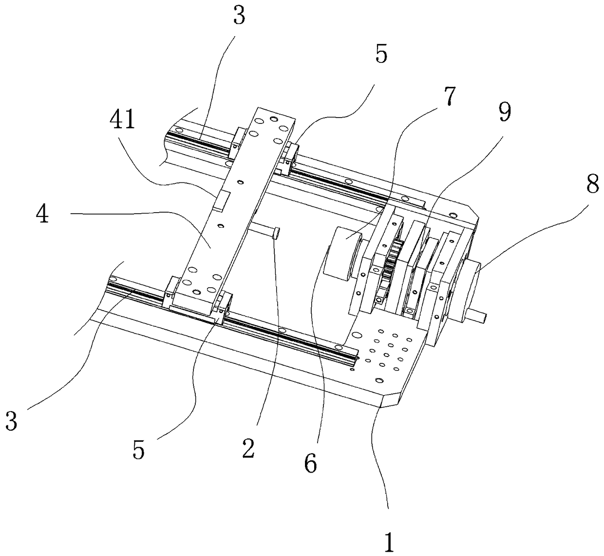
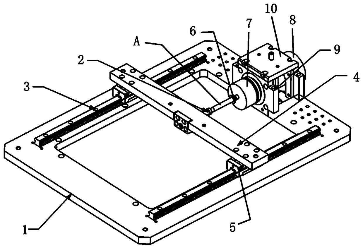
[0037] Such as Figure 1 to Figure 2 As shown, the technical solution of the optical detection device for medical bone nails includes a base 1, a fixed-side thimble 2 and a fixed-rotation assembly.

[0038] Such as figure 1 As shown, the base 1 is equipped with two slide rails 3 arranged parallel to each other; specifically, the base 1 is a rectangular frame-shaped base, and the base 1 has two oppositely arranged long sides, and On the two opposite short sides, the two slide rails 3 are installed on the long edge of the base 1 respectively, and the two slide rails 3 are arranged opposite and parallel to each other.

[0039] Such as figure 1 As shown, the thimble 2 on the fixed side is slidably connected to the two slide rails 3 through a crossbeam 4. Sliders 5 are respectively installed at both ends of the crossbeam 4, and each slide block 5 is along the corresponding slide rail 3. Directional sliding displacement adjustment;

[0040]Specifically: the crossbeam 4 is a cros...


PUM


Abstract

The invention relates to an optical detector for a medical bone nail. The detector comprises a pedestal, a fixed side thimble and a fixed rotation assembly; slide rails are mounted on the pedestal; the fixed side thimble is in sliding connection with the two slide rails via a crossbeam, slide blocks are mounted in the two ends of the crossbeam respectively, and each slide block slides along the slide rails for adjustment; the fixed rotation assembly comprises a rotation side thimble, a thimble chuck and a dial contained hand-operated wheel connected successively, and the dial contained hand-operated wheel is connected with the thimble chuck via a rotating shaft and rotates with the chuck in a linked way; and the rotation side thimble and the fixed side thimble are arranged opposite to eachother in a separate way. The two ends of the bone nail to be detected are clamped, one end relates to a structure capable of displacement adjustment, the application range of the detector can be widened effectively, in the other end of the clamping structure, the dial contained wheel drives the whole bone nail to rotate, and thus, the detector can accurately and rotationally detect the full profile and dimension of the bone nail, and technical problems in the prior art are solved.

Description

technical field [0001] The invention relates to the field of medical bone screw detection, in particular to a medical bone screw that holds the bone screw and rotates the hand wheel so that the part of the bone screw to be tested remains on the same plane, and the optical detection equipment can accurately measure the size of the bone screw from multiple angles. Optical detection device. Background technique [0002] Medical implantable bone nails, also known as fracture fixation screws, are commonly used in clinical orthopedic implants for fixation. Bone nails are usually used for the fixation of internal fractures or dislocations, by directly screwing two different bone pieces or internal implants such as fixed bone plates to fix the fracture, position the bone and promote its healing. Bone nails are used in a wide range of areas, including shoulders, elbows, hips, knees, and spine. For example, pedicle screw systems are used in spinal fusion, and compression bone screws...

Claims


Application Information

Patent Timeline
Patent Type & Authority Applications(China)
IPC IPC(8): G01B11/00G01B11/24
CPCG01B11/00G01B11/24
Inventor 梁长和卢煜文
Owner XIAMEN YINGHAODA PRECISION EQUIP CO LTD
Why Eureka
Try Eureka