Inductor turn-over mechanism

A technology of inductors and connecting rods, which is applied in coil manufacturing and other directions, can solve problems such as difficulty in ensuring the quality of inductors, achieve the effects of preventing breakage or loosening, facilitating welding, and improving work efficiency

Pending Publication Date: 2019-03-08
苏州同岸精工科技有限公司
View PDF0 Cites 2 Cited by
  • Summary
  • Abstract
  • Description
  • Claims
  • Application Information

AI Technical Summary

Problems solved by technology

Because the pole line has a certain hardness, a relatively large pulling force is required to make the pole line close to the inductor at the corners of the inductor, but if the pulling force is too large, the pole line will be torn directly, and the quality of the inductor is difficult to guarantee

Method used


Image

  • Inductor turn-over mechanism
  • Inductor turn-over mechanism
  • Inductor turn-over mechanism

Examples


Embodiment

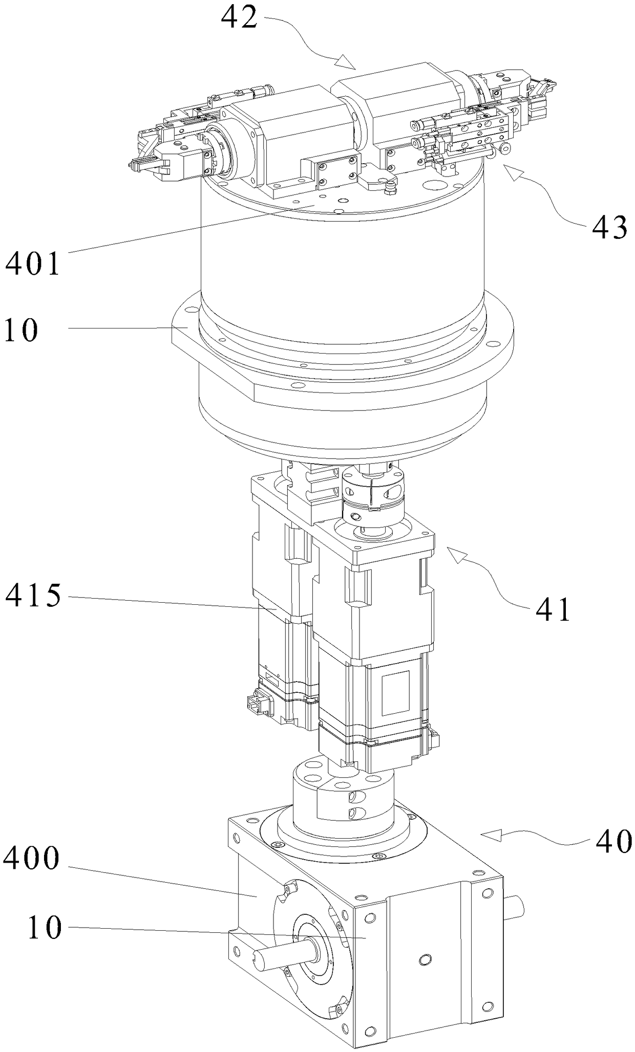
[0032] Reference Figure 1 ~ Figure 5 As shown, the present invention discloses an inductive turning mechanism, which includes a bracket 10 and a steering unit 40, a power unit 41, a turning clamping unit 42 and a wire clamping unit 43 arranged thereon.

[0033] Steering unit 40:

[0034] The above-mentioned steering unit 40 includes a steering drive source 400 and a steering platform 401 that are both arranged on the bracket 10. The steering platform 401 is connected to the free end of the steering driving source 400. The steering drive source 400 can drive the steering platform 401 to rotate, so that the inductance transfer station.

[0035] Power unit 41:

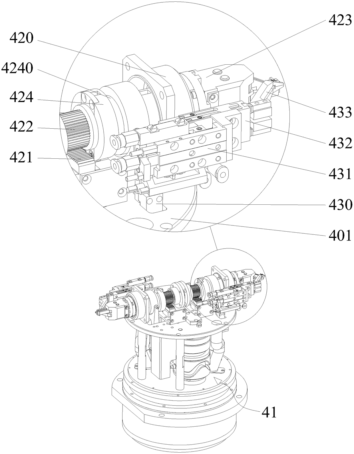
[0036] The aforementioned power unit 41 includes a driving wheel 410, a special-shaped groove, a driving bracket 411, a connecting rod, and a driving source 415. The driving bracket 411 and the driving source 415 are both arranged on the steering platform 401.

[0037] The aforementioned driving source 415 is provided on the s...


PUM


Abstract

The invention discloses an inductor turn-over mechanism comprising a turning unit arranged on a support and used for moving the station of the inductor; the turning unit is provided with wire clampingunits used for clamping the polar wires of the inductor, turn-over clamping units used for clamping and turning over the inductor, and power units used for enabling the wire clamping units to pull the polar wires during the turn-over process of the inductor; there are separately two sets of wire clamping units, turn-over clamping units and power units, which are mirror images of each other.

Description

Technical field [0001] The invention relates to a turning mechanism, in particular to an inductive turning mechanism. Background technique [0002] Wire-wound inductors are one of the commonly used components in circuits, which have the functions of filtering, oscillation, delay, and trapping. After the winding is completed, the polar wire needs to be soldered to the other side of the inductor. Because the polar wire has a certain degree of hardness, a relatively large pulling force is required to make the polar wire close to the inductor at the edges and corners of the inductor. However, if the pulling force is too large, the polar wire will be directly broken, and the quality of the inductor is difficult to guarantee. In addition, the polar line also needs to be accurately welded in the corresponding position to ensure that the post-junction process can proceed normally. Summary of the invention [0003] The technical problem to be solved by the present invention is to provide...

Claims


Application Information

Patent Timeline
Patent Type & Authority Applications(China)
IPC IPC(8): H01F41/10
CPCH01F41/10
Inventor 王帅徐作榜张超
Owner 苏州同岸精工科技有限公司
Why Eureka
Try Eureka