Burr removal device for mortise outlet

A technology for clearing device and tenon and groove, which is applied to the accessories of broaching machine, broaching machine, metal processing equipment, etc. It can solve the problem of burrs at the outlet of tenon and groove, affecting the processing quality and service life of disc parts, and the stress at the outlet of tenon and groove Concentrated area and other problems, to improve the service life, reduce the effect of hardening burr and lattice deformation layer depth

Active Publication Date: 2019-03-12
AECC AVIATION POWER CO LTD
View PDF8 Cites 3 Cited by
  • Summary
  • Abstract
  • Description
  • Claims
  • Application Information

AI Technical Summary

Problems solved by technology

[0003] The object of the present invention is to provide a burr removal device for the outlet of the tenon and groove, which solves the problem of the occurrence of burrs at the out

Method used


Image

  • Burr removal device for mortise outlet
  • Burr removal device for mortise outlet
  • Burr removal device for mortise outlet

Examples


Embodiment

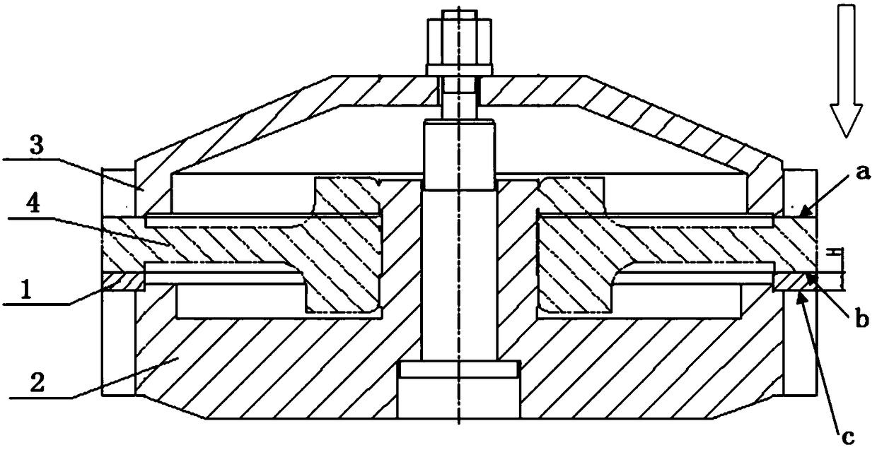
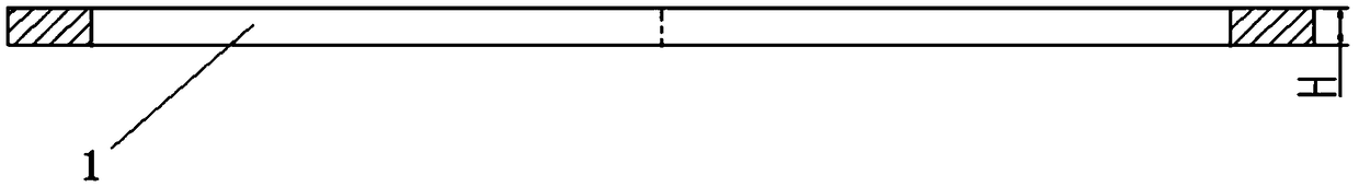
[0037] The chip breaking ring 1 is a ring-shaped part, its inner hole φ535mm is in clearance fit with the intermediate step shaft of the positioning ring 2 in the broaching fixture, one end face fits with the end face of the disc, and the other end face fits with the end face of the positioning ring, The outer circle φ608mm of the chip breaking ring 1 is consistent with the outer circle of the turbine disk, and its height H is selected as 12mm.

[0038] figure 1 Among them, a is the part broach inlet, b is the original broach outlet, and c is the broach outlet of the present invention.

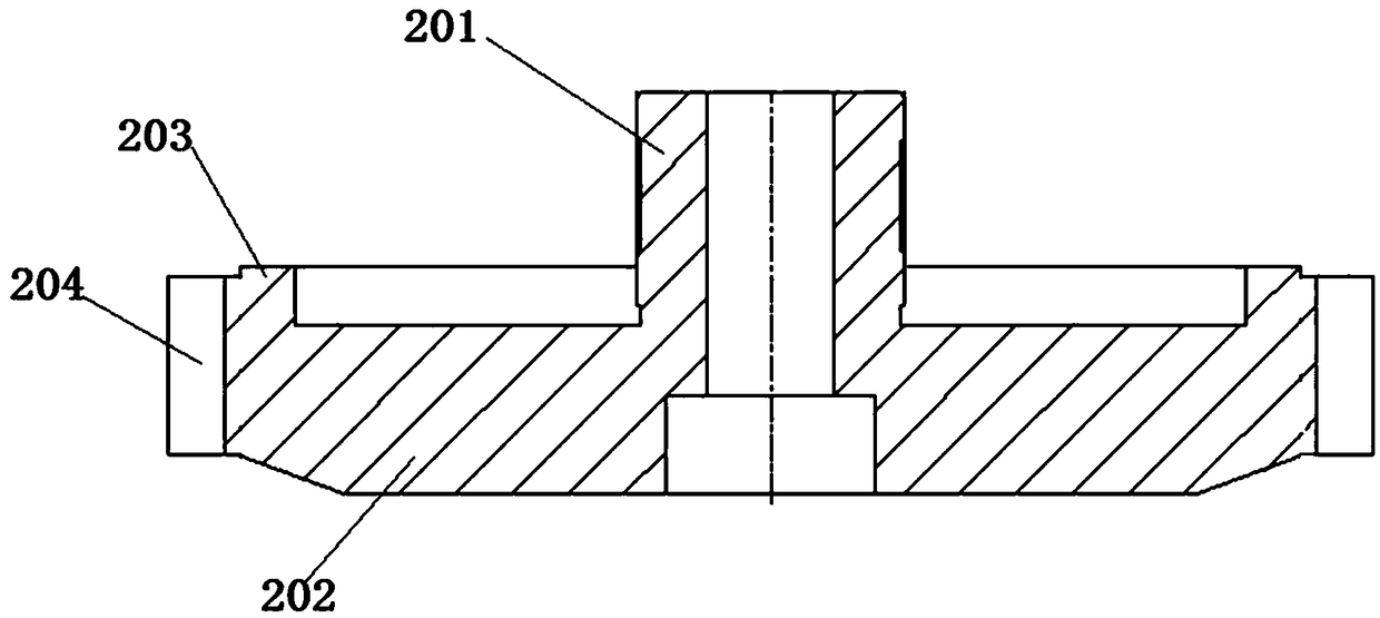
[0039] In the positioning ring 2, the outer circle of the small end shaft of 135.38mm is matched with the inner hole of the part as the radial positioning of the disc parts; the outer circle of the big end is 608mm consistent with the outer circle of the disc; the end face of the chip breaking ring 1 Fitting, the middle step shaft 535mm fits with the inner hole of the chip breaking ring 1; th...


PUM


Abstract

The invention provides a burr removal device for a mortise outlet. The burr removal device comprises a chip breaking ring which is of a circular ring structure, and the chip breaking ring is fixed tothe part below a cleaned plate-part; through arrangement of the chip breaking ring below the plate-part, the outlet end, during broaching of a mortise, extends to the position of the chip breaking ring, so that hard burrs are not liable to generate at the outlet end of the plate-part and the depth of a lattice deformation layer is reduced effectively; and thus the service life of the plate-part isprolonged.

Description

technical field [0001] The invention belongs to the technical field of machining process equipment, and in particular is a burr removal device for tongue and groove outlets. Background technique [0002] The disc parts with axial tenons in the engine are mostly processed by broaching. At present, the materials of disk parts mainly include high-temperature stainless steel, superalloy, titanium alloy and powder metallurgy alloy. When the material of the disc is high temperature alloy or powder metallurgy alloy, there will be burrs at the outlet of the tenon and groove when the tenon and groove are broached. When passing through the outlet of the tongue and groove, the base material of the part is taken out, which deepens the lattice deformation layer of the outlet of the tongue and groove on the part. In the subsequent passivation process of the sharp edge, the deformed area cannot be completely removed, resulting in a stress concentration area, which seriously affects the pr...

Claims


Application Information

Patent Timeline
IPC IPC(8): B23D39/00
CPCB23D39/00
Inventor 吴芳肖飞王素娟胡婷婷张玉宝高惠
Owner AECC AVIATION POWER CO LTD
Why Eureka
Try Eureka