Weft yarn clamping mechanism

A technology of clamping mechanism and weft yarn, which is applied in the field of weaving, can solve the problems that the production efficiency cannot be effectively improved, and achieve the effect of shortening the reciprocating time and improving the production efficiency

Active Publication Date: 2019-03-12
NANJING FIBERGLASS RES & DESIGN INST CO LTD
View PDF8 Cites 5 Cited by
  • Summary
  • Abstract
  • Description
  • Claims
  • Application Information

AI Technical Summary

Problems solved by technology

[0004] In the weaving process, the pulling of the weft yarn is still mainly done manually with simple tools, and the production efficiency cannot be effectively improved.

Method used


Image

  • Weft yarn clamping mechanism
  • Weft yarn clamping mechanism
  • Weft yarn clamping mechanism

Examples


Embodiment 1

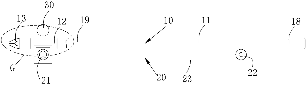
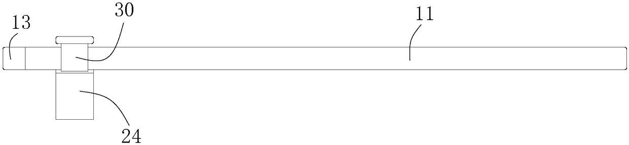
[0047] see Image 6 , a weft yarn clamping mechanism 100, which is used to clamp and pull the weft yarn, and is installed on the weft insertion mechanism of a 2.5D knitting machine. Weft mechanism 110, the weft yarn clamping mechanism 100 includes a belt conveyor 20, a clamping rod 10 and a pressing block 30, and the belt conveyor is fixedly installed on the support of the weft insertion mechanism.

[0048] see Figure 2-Figure 5 The belt conveyor 20 includes a driving wheel 21, a driven wheel 22, and a servo motor 24 that drives the driving wheel to rotate. Wherein the driving wheel 21 and the driven wheel 22 are all installed on the support through the rotating shaft, and the servo motor 21 is also installed on the support.

[0049] The clamping rod 10 is arranged on the belt 23 of the belt conveyor, and the pressing block 30 is rotatably installed on the support, and the pressing block 30 compresses the clamping rod 10 on the belt; when the belt rotates, it can drive the ...

Embodiment 2

[0069] The mechanical structure of this embodiment is the same as that of Embodiment 1, and the difference is that when pulling the weft yarn, the operation mode of the chuck is different, and the specific description is as follows:

[0070] Such as Figure 7 As shown, in this embodiment, between the belt conveyor 820 and the weft selection mechanism 120, a chuck starting point A2 position 821, a chuck retraction point B2 position 822, an intermediate stop point E position 825, and a middle stop point E position 825 are arranged sequentially. Retraction point F position 826, chuck opening point C2 position 823 and chuck closing point D2 position 824; the weft selection mechanism has a second pressure plate 182 for pressing the weft yarn;

[0071] Before the work starts, the chuck is on standby at position 821 of the starting point A2 of the chuck. When working, driven by the belt conveyor 820, the clamping rod 810 starts to move, firstly the chuck moves from the starting point...


PUM


Abstract

The invention discloses a weft yarn clamping mechanism. The mechanism comprises a belt conveyer, a clamping rod and a pressing block, wherein the belt conveyer is fixedly mounted on a bracket of a weft guiding mechanism; an annular belt capable of cyclically rotating is arranged on the belt conveyor, the clamping rod is arranged on the belt of the belt conveyor, and the pressing block is rotatablymounted on the bracket and presses the clamping rod on the belt; the clamping rod comprises a straight rod-shaped rapier, the two ends of the rapier are adopted as a clamping end and a tail end respectively, and an inner cavity is formed in the clamping end of the rapier and provided with an opening in the end face of the clamping end; an air cylinder is mounted in the inner cavity, a clamping head is mounted at the opening of the inner cavity. The clamping head comprises two clamping jaws which are oppositely arranged, and when a piston rod moves, the clamping jaws can be driven to rotate, so that engaging ends of the two clamping jaws are abutted together. The mechanism can be connected with an automatic control system, and the production efficiency is effectively improved.

Description

technical field [0001] The invention relates to a 2.5D prefabricated body weft yarn clamping mechanism, which is used in a 2.5D automatic weaving machine and belongs to the technical field of weaving. Background technique [0002] 2.5D weaving manufacturing molding is a new type of weaving technology. It is an overall structure formed by yarn bundles distributed in three-dimensional space along the warp and weft directions perpendicular to each other and interwoven together, especially as a reinforcement. Composite components have many advantages such as light weight, high strength, and excellent mechanical properties. At present, they have been widely used in many fields such as aerospace, national defense, transportation, and energy, and are expanding to civilian fields. [0003] 2.5D weaving equipment such as figure 1 Shown is the basic manufacturing schematic diagram of 2.5D weaving. During the manufacturing process, the warp yarn bundle 1 is drawn out from the warp cr...

Claims


Application Information

Patent Timeline
Patent Type & Authority Applications(China)
IPC IPC(8): D03D47/23
CPCD03D47/23
Inventor 赵谦朱金龙李超王再勇张立泉
Owner NANJING FIBERGLASS RES & DESIGN INST CO LTD
Why Eureka
Try Eureka