Light-emitting device light guiding lens and light-emitting device

A light-emitting device and lens technology, applied in the field of semiconductors, can solve problems such as unfavorable miniaturization, ultra-thinning of lamps, beam angles that cannot meet application requirements, large space, etc. wide range of effects

Pending Publication Date: 2019-03-12
GUANGDONG INST OF SEMICON IND TECH
View PDF6 Cites 0 Cited by
  • Summary
  • Abstract
  • Description
  • Claims
  • Application Information

AI Technical Summary

Problems solved by technology

[0002] In modern lighting applications, light-emitting diode (LED) light sources are gradually replacing traditional light sources due to their advantages of energy saving, high efficiency, and good stability. need
However, when optical devices such as reflectors or lenses are used to control the light emitted by LEDs, the overall device needs to occupy a large space, which is not conducive to the development of miniaturization and ultra-thinning of lamps.

Method used


Image

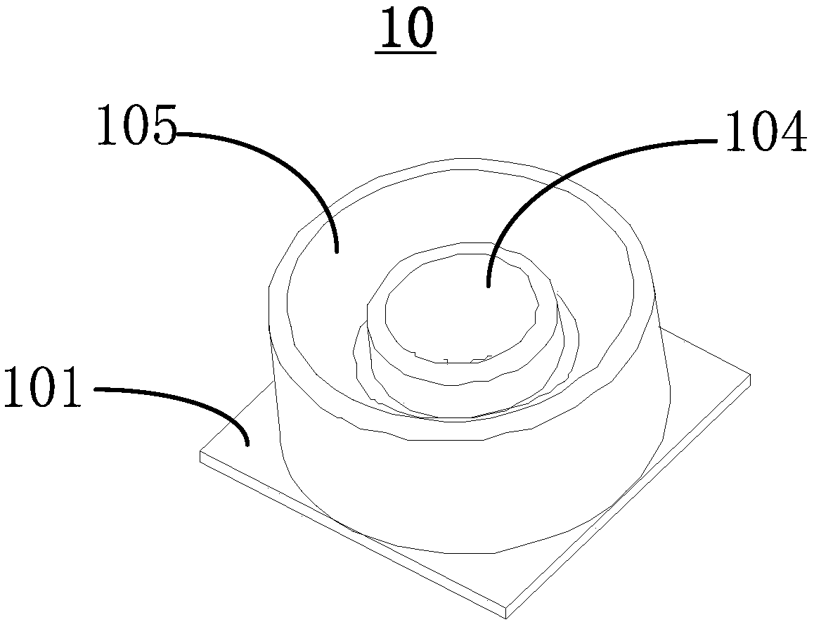
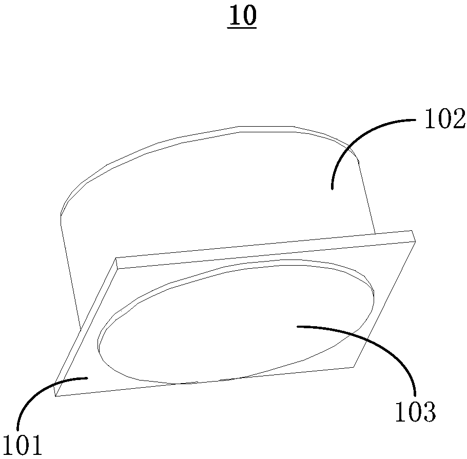
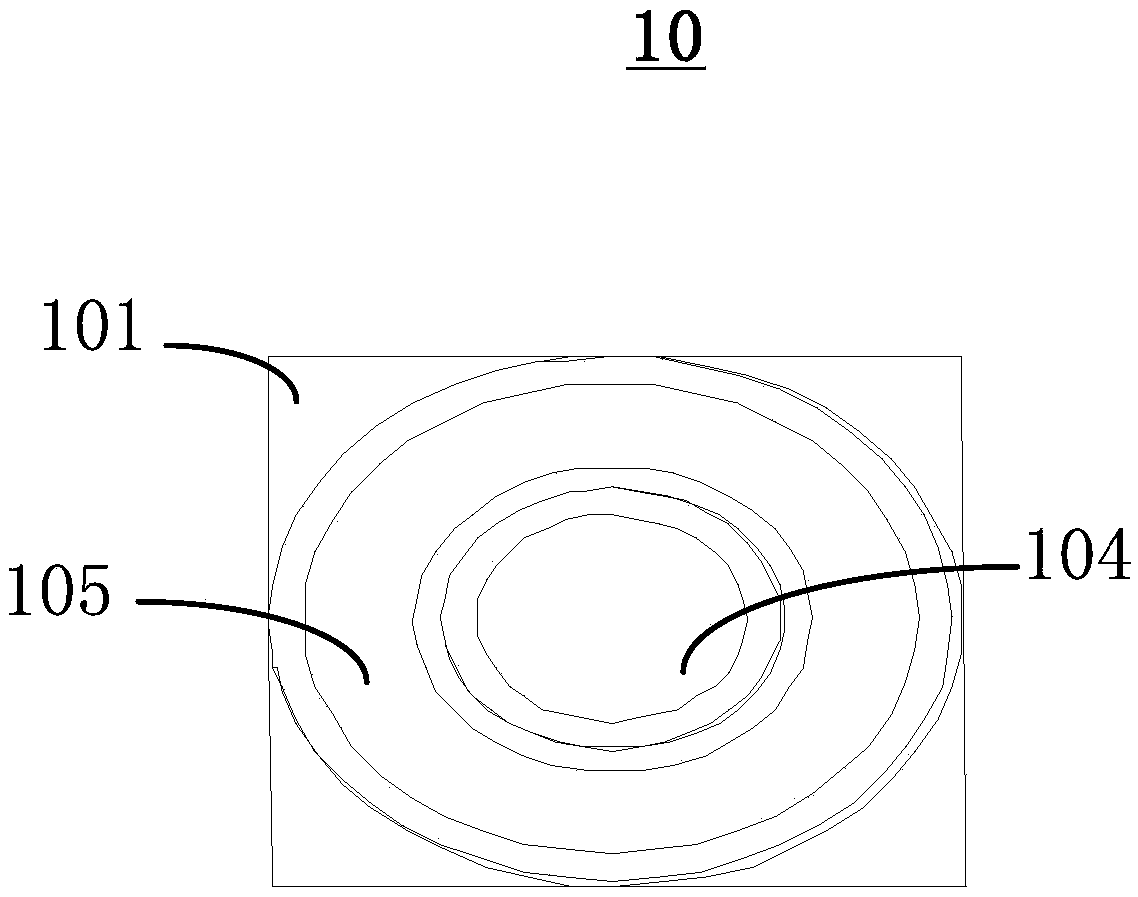
  • Light-emitting device light guiding lens and light-emitting device
  • Light-emitting device light guiding lens and light-emitting device
  • Light-emitting device light guiding lens and light-emitting device

Examples


Embodiment Construction

[0034] The following will clearly and completely describe the technical solutions in the embodiments of the present invention with reference to the accompanying drawings in the embodiments of the present invention. Obviously, the described embodiments are only some, not all, embodiments of the present invention. The components of the embodiments of the invention generally described and illustrated in the figures herein may be arranged and designed in a variety of different configurations. Accordingly, the following detailed description of the embodiments of the invention provided in the accompanying drawings is not intended to limit the scope of the claimed invention, but merely represents selected embodiments of the invention. Based on the embodiments of the present invention, all other embodiments obtained by those skilled in the art without making creative efforts belong to the protection scope of the present invention.

[0035] It should be noted that like numerals and let...


PUM


Abstract

The invention provides a light-emitting device light guiding lens and a light-emitting device and relates to the technical field of semiconductor devices. By means of a first hammer light guiding groove and a second light guiding groove arranged in the circumferential direction, light emitted by a light source can be distributed, and refraction or total reflection of light occurs at an interface of the light guiding lens, so that the original propagation direction of the light changes, the coverage range of the light radiated from the light-emitting device light guiding lens is wider, and theillumination range of the light source is larger. The light-emitting device light guiding lens is simple in structure, low in manufacturing cost, and beneficial to miniaturization and ultra-thinness of the light source.

Description

technical field [0001] The invention relates to the technical field of semiconductors, in particular to a light guide lens of a light emitting device and a light emitting device. Background technique [0002] In modern lighting applications, light-emitting diode (LED) light sources are gradually replacing traditional light sources due to their advantages of energy saving, high efficiency, and good stability. need. However, when optical devices such as reflectors or lenses are added to control the light emitted by LEDs, the overall device needs to occupy a large space, which is not conducive to the development of miniaturization and ultra-thinning of lamps. Contents of the invention [0003] In view of this, the present invention provides a light guide lens for a light emitting device and a light emitting device, which have a simple structure and can achieve better control over light emitted by a light source. [0004] The technical scheme provided by the invention is as ...

Claims


Application Information

Patent Timeline
Patent Type & Authority Applications(China)
IPC IPC(8): F21K9/69F21V5/04F21Y115/10
CPCF21K9/69F21V5/04F21Y2115/10
Inventor 夏智锋许毅钦陈志涛张志清张强古志良洪宇许平
Owner GUANGDONG INST OF SEMICON IND TECH
Why Eureka
Try Eureka