Multi-energy complementary air source heat pump

An air source heat pump, multi-energy technology, applied in heat pumps, solar thermal energy, solar collectors, etc., can solve the problems of reduced efficiency, reduced heating efficiency, increased compressor compression ratio, etc., to improve work efficiency and reduce operation. cost, the effect of improving energy efficiency ratio

Pending Publication Date: 2019-03-12
赵昕
View PDF0 Cites 0 Cited by
  • Summary
  • Abstract
  • Description
  • Claims
  • Application Information

AI Technical Summary

Problems solved by technology

In the northern region, the outdoor temperature is very low in winter. As far as the air source heat pumps currently on the market are concerned, the heating capacity of the system drops rapidly as the outdoor ambient temperature drops. When the outdoor temperature is very low, the heating capacity of the system cannot even meet the heating requirements. requirements, causing the system to fail to function properly
[0003] In addition, the drop of outdoor temperature in winter will also reduce the efficiency of the compressor. When the outdoor temperature drops, the evaporating temperature and evaporating pressure will decrease, while the condensing pressure will not change much, which will inevitably lead to an increase in the compression ratio of the compressor and a great decrease in heating efficiency. At the same time, the increase of the compression ratio will cause the discharge temperature of the compressor to rise continuously, the power consumption of the compressor will increase, and the efficiency will decrease. Long-term high discharge temperature will also cause damage to the compressor and seriously affect the service life of the compressor.

Method used


Image

  • Multi-energy complementary air source heat pump
  • Multi-energy complementary air source heat pump
  • Multi-energy complementary air source heat pump

Examples


Embodiment Construction

[0023] Below in conjunction with accompanying drawing and embodiment, further elaborate the present invention. In the following detailed description, certain exemplary embodiments of the invention are described by way of illustration only. Needless to say, those skilled in the art would realize that the described embodiments can be modified in various different ways, all without departing from the spirit and scope of the present invention. Accordingly, the drawings and description are illustrative in nature and not intended to limit the scope of the claims.

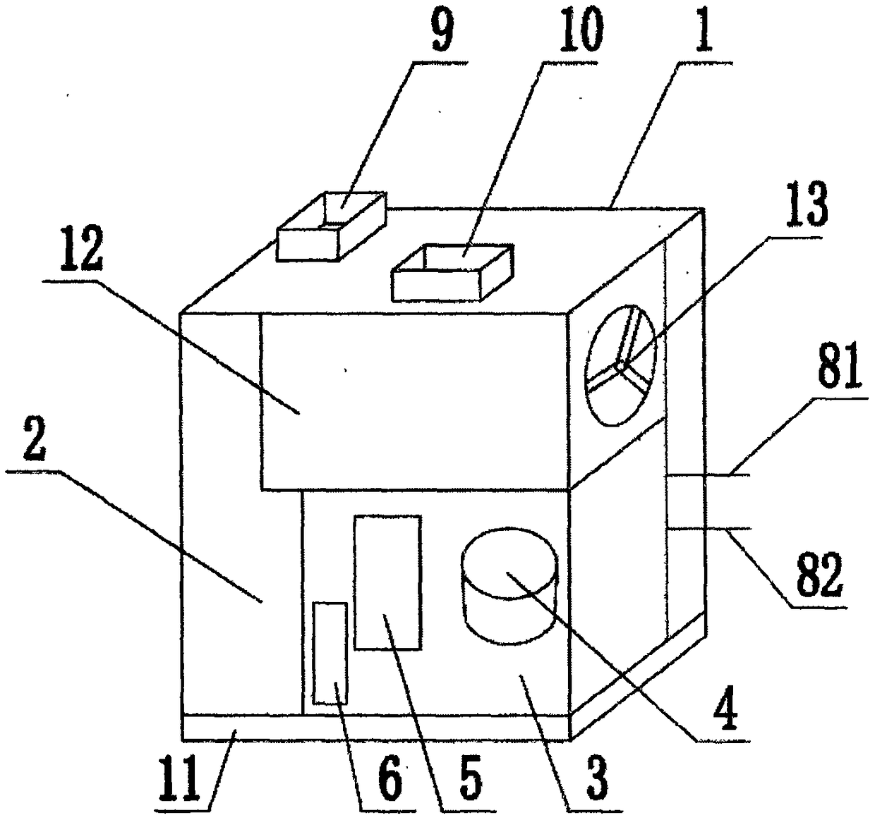
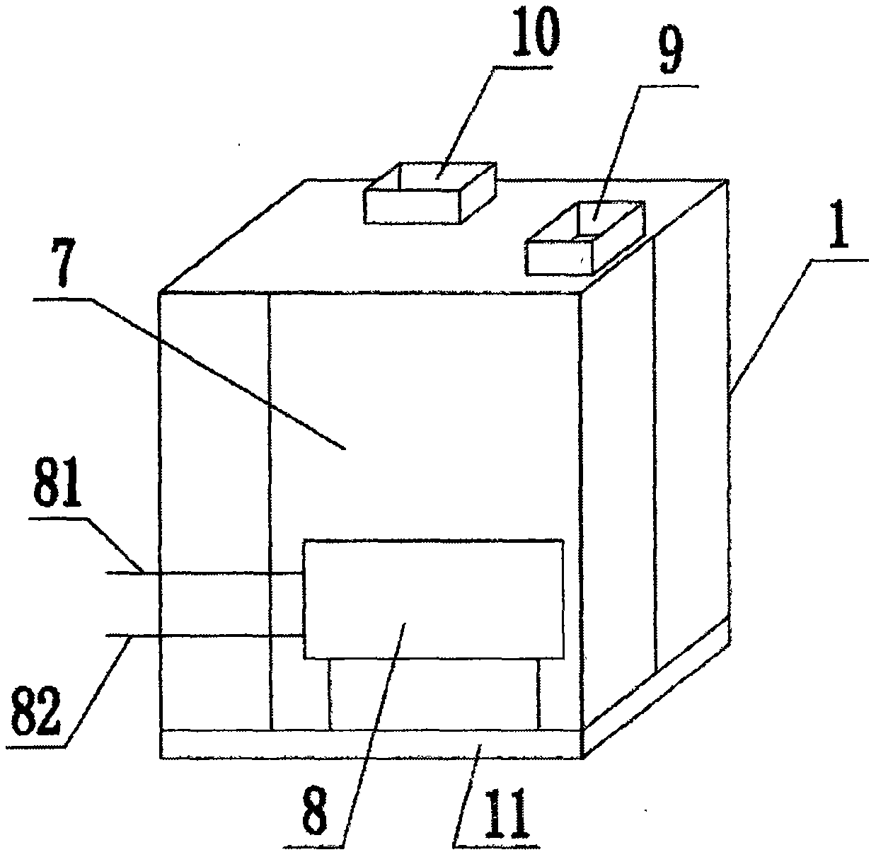
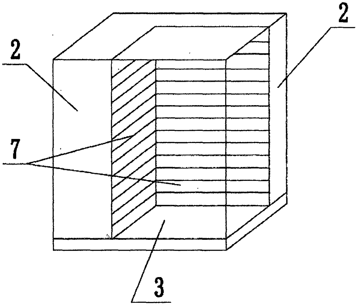
[0024] Such as Figure 1 to Figure 3 As shown, the multi-energy complementary air source heat pump according to this embodiment includes an assembled frame 1, a condenser fin 7 vertically arranged inside the assembled frame 1, and a condenser fin 7 arranged on the top of the assembled frame 1. Or the air inlet 9 and the air outlet 10 of the side wall, the assembled skeleton 1 is a frame structure and each surface is cov...


PUM


Abstract

The invention discloses a multi-energy complementary air source heat pump which comprises an assembled skeleton, condenser fins vertically arranged inside the assembled skeleton, air inlets and air outlets. The air inlets and the air outlets are arranged in the top or side walls of the assembled skeleton, the assembled skeleton is of a frame structure, each surface is covered with a heat insulation board, the condenser fins divide the interior of the assembled skeleton into two parts including a heat chamber and a cold discharge chamber, the heat chamber is internally provided with heat-supplementing heat sink fins, the cold discharge chamber is internally provided with a power box, a centrifugal fan, a heat exchanger, a compressor, a gas-liquid separator and a connecting pipe, and the power box is electrically connected with the compressor, the centrifugal fan, the heat exchanger and the gas-liquid separator. The multi-energy complementary air source heat pump is additionally providedwith a shell heat preservation box and a heat-supplementing heat sink, the working environment of the air source heat pump can be changed, the energy-efficiency ratio of the air source heat pump canbe improved under the low temperature state, the aim of better reducing fossil energy consumption is achieved, and the wide applicability is achieved.

Description

technical field [0001] The invention relates to the technical field of air source heat pumps, in particular to a multi-energy complementary air source heat pump. Background technique [0002] At present, air source heat pumps have been widely used in many areas of our country. In the southern region, the outdoor temperature is generally not lower than minus 5°C in winter, and the indoor heat demand is not large. Air source heat pumps work well and have high energy efficiency. In the northern region, the outdoor temperature is very low in winter. As far as the air source heat pumps currently on the market are concerned, the heating capacity of the system drops rapidly as the outdoor ambient temperature drops. When the outdoor temperature is very low, the heating capacity of the system cannot even meet the heating requirements. demand, causing the system to fail to function properly. [0003] In addition, the drop of outdoor temperature in winter will also reduce the efficien...

Claims


Application Information

Patent Timeline
Patent Type & Authority Applications(China)
IPC IPC(8): F25B30/06F25B30/02F25B43/00F24S10/00F24D17/02F24D15/04F24F5/00
CPCF25B30/06F24D15/04F24D17/02F24F5/001F25B30/02F25B43/00
Inventor 赵昕赵振田蔡良伯吕令生
Owner 赵昕
Why Eureka
Try Eureka