Locking control method for locking device

A technology of a locking device and a control method, which is applied in general control systems, program control, computer control, etc., can solve the problems of failure to meet high reliability requirements, failure of relays, low reliability, etc., and achieve improved stability and automatic control. detection capability, noise reduction, and high reliability

Inactive Publication Date: 2019-03-12
JIUJIANG JINGDA MEASUREMENT TECH
View PDF0 Cites 2 Cited by
  • Summary
  • Abstract
  • Description
  • Claims
  • Application Information

AI Technical Summary

Problems solved by technology

The locking control method adopted by the current locking device mostly adopts relay control, but in the production process of the relay, some organic excess will inevitably be brought in, and these organic excess will cause the relay to fail during the working process. phenomenon, and relays are electronic components with low reliability, so they cannot meet the high reliability requirements when used in aerospace instruments and equipment

Method used


Image

  • Locking control method for locking device
  • Locking control method for locking device
  • Locking control method for locking device

Examples


Embodiment Construction

[0023] The present invention will be described in further detail below in conjunction with the embodiments and with reference to the accompanying drawings.

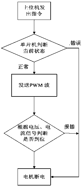
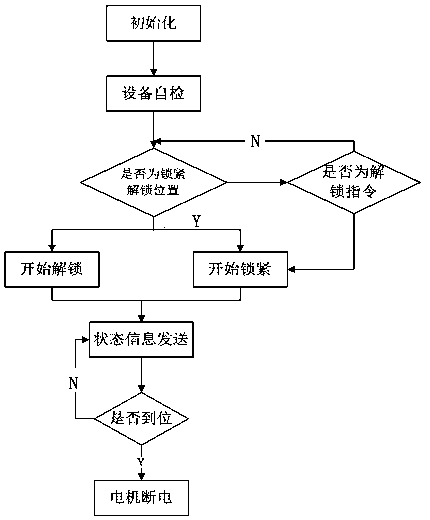
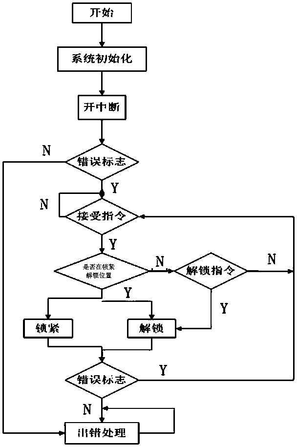
[0024] A control method for a locking device, characterized in that: the locking device includes a photoelectric switch, a comparator, a single-chip microcomputer (ATM16), a drive integrated circuit (LMD18200), a power module and a motor, wherein: the output terminal of the photoelectric switch is connected to a comparison The first input terminal of the comparator, the second input terminal of the comparator is connected to the standard signal, the output terminal of the comparator is connected to the signal input terminal of the single-chip microcomputer, and the position information of the mechanical platform is read through the photoelectric switch, and the light containing the position information is read. The signal is converted into an electrical signal, which is sent to the first input terminal of the comparator, a...


PUM


Abstract

The invention relates to a locking method for a locking device. The locking device comprises an optoelectronic switch, a comparator, a single chip microcomputer, a driving integrated circuit, a powersupply module and a motor, and four modules of a main program module, a serial port receiving interrupting module, a serial port transmitting interrupting module and a software timing interrupting module are arranged in the single chip microcomputer. The optoelectronic switch reads position information of a mechanical platform body, the comparator processes a signal and feeds back the signal to the single chip microcomputer, and after the single chip microcomputer judges the position signal, a PWM pulse width wave is sent to a driving chip to control the motor to rotate. The locking control method adopts a pulse width modulation control mode (PWM), and not only has the advantages that the noise influence is low, and the transmitting distance is long, but also utilizes a small pulse wave tocontrol stalling of the motor in the locking process, and therefore high reliability of locking is achieved. The operation is convenient and easy to implement, and not only is quick locking of the locking device achieved, but also high reliability of locking of the locking device is achieved through continuous impulse waves in the locking process.

Description

technical field [0001] The invention relates to a locking device, in particular to a locking control method of the locking device. Background technique [0002] As a high-reliability in-position control mechanism, the locking device is used in more and more instruments and equipment that require precise locking, such as inertial groups. These instruments and equipment often work in harsh environments. The locking control method adopted by the current locking device mostly adopts relay control, but in the production process of the relay, some organic excess will inevitably be brought in, and these organic excess will cause the relay to fail during the working process. phenomenon, and relays are electronic components with low reliability, so they cannot meet the high reliability requirements when used in aerospace instruments and equipment. Contents of the invention [0003] The object of the present invention is to provide a locking control method for a locking device with...

Claims


Application Information

Patent Timeline
Patent Type & Authority Applications(China)
IPC IPC(8): G05B19/042
CPCG05B19/0423
Inventor 吴昊王晓卿任梦晴陈先梅彭爱民陈悦
Owner JIUJIANG JINGDA MEASUREMENT TECH
Why Eureka
Try Eureka