Dynamic alloy bar straightening mechanism, system and method, and dynamic alloy bar automatic straightening method

A technology of alloy bar and straightening mechanism, which is applied in the direction of metal processing equipment, forming tools, manufacturing tools, etc., can solve the problems of high strength of metal materials, increase of equipment tonnage, large tensile force, etc., and meet the requirements of precision and operation Convenient and meet the effect of mass production

Active Publication Date: 2019-03-15
西安圣泰金属材料有限公司
View PDF7 Cites 4 Cited by
  • Summary
  • Abstract
  • Description
  • Claims
  • Application Information

AI Technical Summary

Problems solved by technology

The main disadvantage of traditional stretch straightening is that the metal material straightened at room temperature has high strength, which requires a large tensile force and increa

Method used


Image

  • Dynamic alloy bar straightening mechanism, system and method, and dynamic alloy bar automatic straightening method
  • Dynamic alloy bar straightening mechanism, system and method, and dynamic alloy bar automatic straightening method

Examples


Embodiment 1

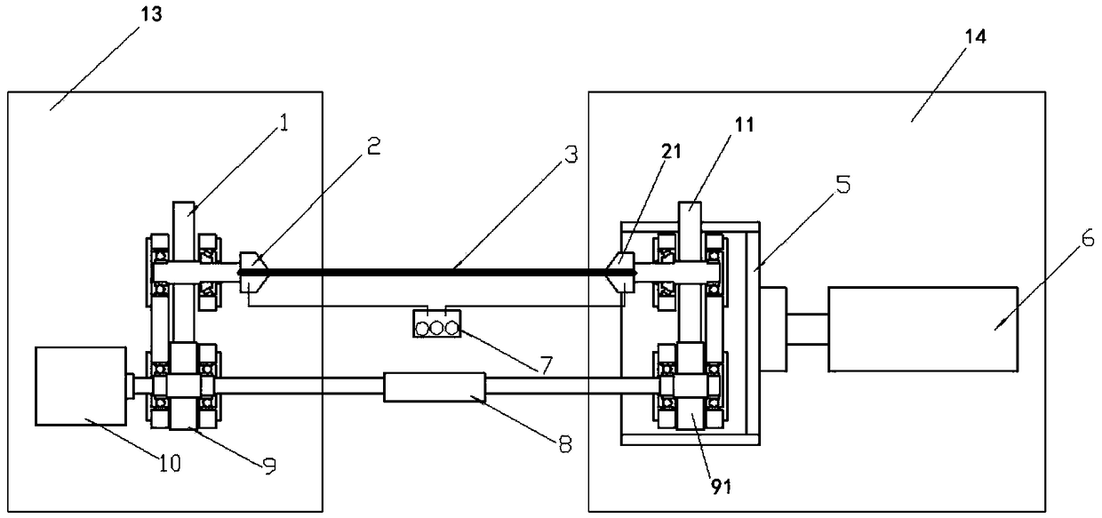
[0043] like figure 1 As shown, in this embodiment, a dynamic alloy bar straightening system includes the dynamic alloy bar straightening mechanism, the first rotating chuck 2 and the first large gear 1 are fixed on the fixed base 13 through bearings Above, the deceleration motor 10 is fixed on the fixed base 13, the first pinion 9 is fixed on the fixed base 13 through bearings; the second rotary chuck 21 and the second large gear 11 are fixed on the sliding seat 5 through bearings, and the second small The gear 91 is fixed on the sliding seat 5 through a bearing, and the sliding seat 5 is slidably connected to the stretching base 14 ; the hydraulic device 6 is fixed on the stretching base 14 .

[0044] When the system of this embodiment is in use, it includes the following steps:

[0045] S1: Fix the alloy bar on the first rotary chuck 2 and the second rotary chuck 21;

[0046]S2: The user adjusts the current according to the alloy grade and diameter of the alloy rod to make...

Embodiment 2

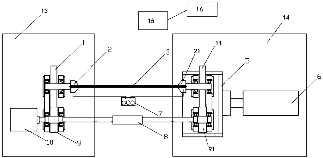
[0059] like figure 2 As shown, in this embodiment, a dynamic alloy rod straightening system includes the dynamic alloy rod straightening mechanism, a PLC controller 15, and a client terminal 16 electrically connected to the PLC controller 15; the first The rotary chuck 2 and the first large gear 1 are fixed on the fixed base 13 through bearings, the reduction motor 10 is fixed on the fixed base 13, and the first pinion 9 is fixed on the fixed base 13 through bearings; the second rotary chuck 21, The second large gear 11 is fixed on the sliding seat 5 through a bearing, the second pinion 91 is fixed on the sliding seat 5 through a bearing, and the sliding seat 5 is slidably connected to the stretching base 14; the hydraulic device 6 is fixed on the stretching base 14 Above, the PLC controller 15 is electrically connected to the current controller 7, and the PLC controller 15 is also electrically connected to the hydraulic device 6, the reduction motor 10, and the power supply....


PUM


Abstract

The invention discloses a dynamic alloy bar straightening mechanism, system and method and a dynamic alloy bar automatic straightening method. The dynamic alloy bar straightening mechanism comprises afixing assembly and a stretching assembly; the fixing assembly comprises a first rotary chuck (2), a first big gear (1) coaxially arranged with a rotary shaft of the first rotary chuck, a first smallgear (9) in transmission connection with the first big gear (1), and a speed reduction motor (10) with a power output shaft provided with the first small gear (9); and the stretching assembly comprises a second rotary chuck (21), a second big gear (11) coaxially arranged with a rotary shaft of the second rotary chuck (21), and a second small gear (91) in transmission connection with the second big gear (11). The problem that bars are softened and droop to be bent to affect the straightness accuracy due to straightening temperature rising can be effectively solved. The methods have the characteristics of being convenient to implement, rapid, mechanical and the like, operation is convenient, and the batch production and precision requirements can be met.

Description

technical field [0001] The invention relates to the technical field of metal profile straightening, in particular to a dynamic alloy bar straightening mechanism, system, straightening method, and automatic straightening method. Background technique [0002] The straightening of metal bars usually adopts methods such as skewed roll straightening and stretching straightening. [0003] Slant roll straightening includes two-roll and multi-roll straightening. This method is the most commonly used method for straightening metal bars. Its principle is that after the metal bars pass through the roll gap, the bending curvature is changed to achieve the purpose of straightening. The straightening accuracy and production efficiency are relatively high, and the main disadvantage is that the equipment is complicated. , the production cost is high, and at the same time, the product generates a large internal stress during the straightening process. After the product is placed for a long ...

Claims


Application Information

Patent Timeline
IPC IPC(8): B21D3/12B21D37/16
CPCB21D3/12B21D37/16
Inventor 张温馨曹继敏贺峰罗乾伟王戈
Owner 西安圣泰金属材料有限公司
Why Eureka
Try Eureka