
Plate cutting device

A cutting device and plate technology, applied in the field of parts processing, can solve problems such as low cutting accuracy, human injury, and potential safety hazards, and achieve the effect of facilitating centralized collection and reducing cutting errors

Active Publication Date: 2019-03-15
CHONGQING JIANZHU COLLEGE
View PDF5 Cites 2 Cited by
  • Summary
  • Abstract
  • Description
  • Claims
  • Application Information

AI Technical Summary

Problems solved by technology

In this operation method, human hands are used to press the plate, which has potential safety hazards of hand injury, and because of manual feeding, there are errors during feeding, and the sawing accuracy cannot be guaranteed.
[0003] The traditional plate cutting method is labor-intensive for workers, making it difficult to achieve mass production. At the same time, it is easy to lead to low cutting accuracy and waste of plates; at the same time, a large amount of dust will be generated during the cutting process, and the dust is easy to diffuse in the air, which will cause The processing environment is harsh, and workers can easily inhale sheet dust into the lungs, which will cause irreversible damage to the human body

Method used


Image

  • Plate cutting device
  • Plate cutting device

Examples


Embodiment Construction

[0023] Further detailed explanation through specific implementation mode below:

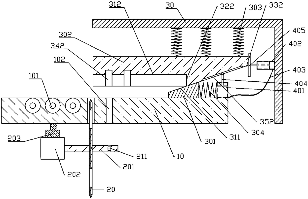
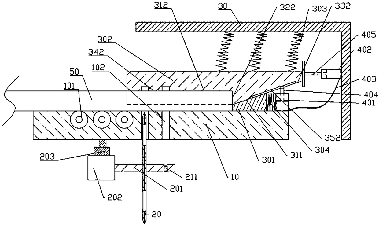
[0024] The reference signs in the accompanying drawings of the description include: machine table 10, transmission wheel 101, knife hole 102, cutting knife 20, rotating shaft 201, socket 211, motor 202, third cylinder 203, frame 30, block 301, first Wedge surface 311, pressure block 302, horizontal surface 312, vertical surface 322, second wedge surface 332, knife relief groove 342, chute 352, extension spring 303, compression spring 304, first cylinder 401, second cylinder 402, connection Tube 403 , first slide bar 404 , second slide bar 405 , plate 50 .

[0025] The embodiment is basically as attached figure 1 And attached figure 2 Shown: a plate cutting device, including a machine table 10, a cutting knife 20, a rotating transmission wheel 101, a rotating shaft 201, a control unit, a motor 202 that drives the rotating shaft 201 to rotate, and a limiting mechanism for limiting the plate 50. ...


PUM


Abstract

The invention relates to the field of part processing and particularly discloses a plate cutting device. The plate cutting device comprises a machine table and cutters, and further comprises a rotating conveying wheel and a limiting mechanism for limiting plates. The conveying wheel is rotationally installed on the machine table and is in contact with the plates. The machine table is provided witha plurality of cutter holes allowing the cutters to penetrate through, and the distances between the cutter holes and the limiting mechanism are different. The cutting device in the scheme can perform accurate cutting on the plates.

Description

technical field [0001] The invention belongs to the field of component processing, and in particular relates to a plate cutting device. Background technique [0002] With the vigorous development of the furniture industry, the demand and usage of wooden panels continue to rise, and the requirements for panel cutting equipment are also gradually increasing. In the process of sheet material processing, a sliding table saw is generally used as the cutting equipment for the sheet material. During the sawing process, the worker puts the sheet material on the workbench, and then uses manual feeding to push the sheet material to the direction of the cutting knife. At this time, Manually control the distance between the end of the plate and the cutting knife to control the cutting length of the plate. In this mode of operation, human hands are used to press down on the plate, which has potential safety hazards of hand injury, and because the material is fed manually, there are erro...

Claims


Application Information

Patent Timeline
Patent Type & Authority Applications(China)
IPC IPC(8): B27C5/02
CPCB27C5/02
Inventor 姚长鑫刘谋黎曾乐
Owner CHONGQING JIANZHU COLLEGE
Learn More