
self-embedded retaining wall

A retaining wall and self-embedded technology, which is applied in container cultivation, construction, artificial islands, etc., can solve problems such as inconvenient construction, and achieve the effects of convenient installation, sufficient water, and high installation efficiency

Inactive Publication Date: 2021-01-12
河海大学设计研究院有限公司
View PDF1 Cites 0 Cited by
  • Summary
  • Abstract
  • Description
  • Claims
  • Application Information

AI Technical Summary

Problems solved by technology

[0006] The purpose of the present invention is to provide a self-embedded retaining wall, which solves the technical problem of inconvenient construction caused by filling soil alone. The retaining wall is easy to construct and fast to install.

Method used

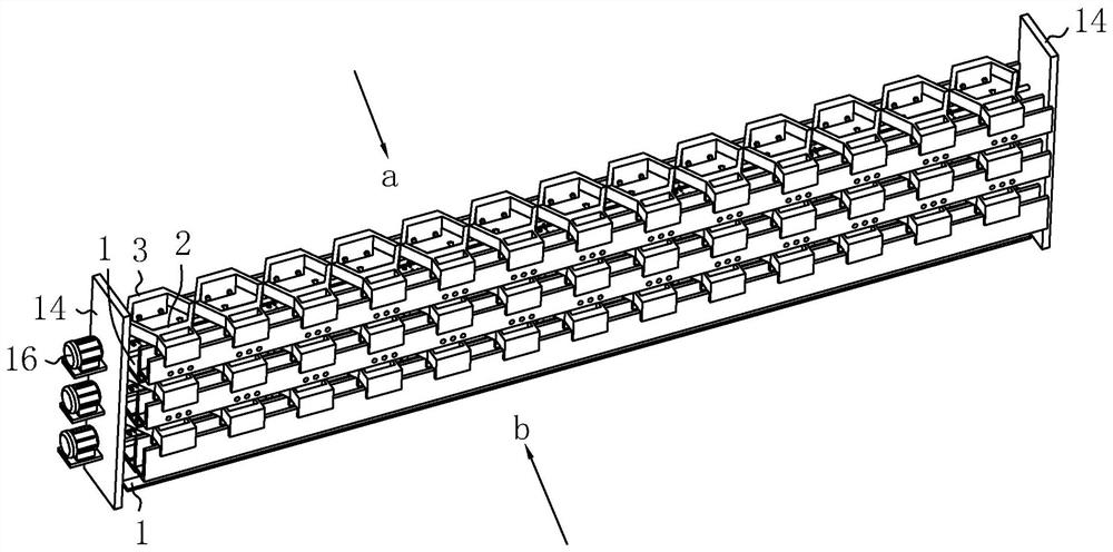

Image

  • self-embedded retaining wall
  • self-embedded retaining wall
  • self-embedded retaining wall

Examples


Embodiment 1

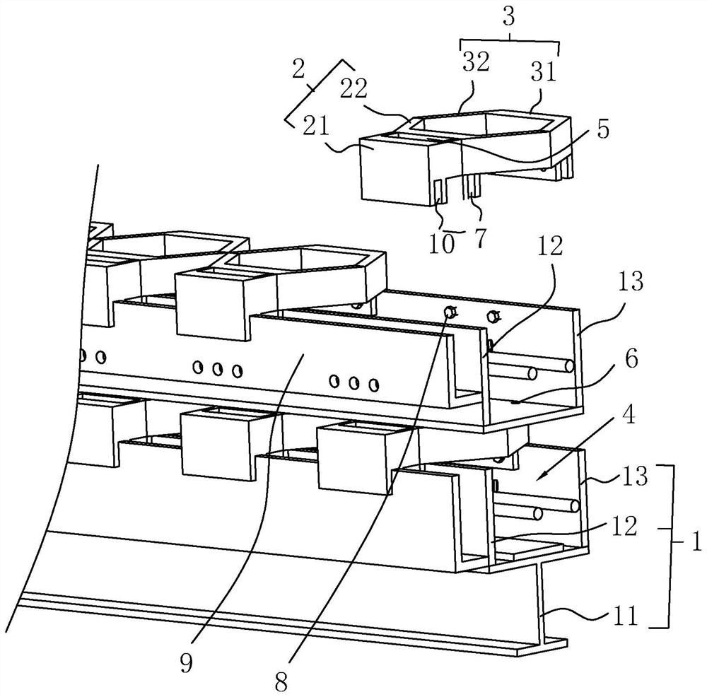
[0037] refer to figure 1 , is a self-embedded retaining wall disclosed by the present invention, comprising a bearing frame 1 screwed on the old wall, a first splicing body 2 inserted on the bearing frame 1 and facing the water side, and a first joint body 2 facing the filling side The second splicing body 3, the first splicing body 2, and the second splicing body 3 are surrounded to form a closed ring body, and the carrier frame 1 is used to install on the old wall, and the carrier frame 1 is used as a base to ensure that the first splicing body 2 and the second splicing body The body 3 has the same reference plane when installed, and then the first splicing body 2 and the second splicing body 3 are plugged on the carrier frame 1. Compared with the construction method of using a single brick to stack up in the prior art, the construction method is greatly improved. The convenience and quickness of forming the self-embedded retaining wall.

[0038] refer to figure 1 and fi...

Embodiment 2

[0044] A self-embedded retaining wall, the construction method of the retaining wall comprises the following steps:

[0045] (1) Clean the dust on the surface of the old wall, and screw the lower surface of the I-beam to the old wall;

[0046] (2) Weld the first board and the second board to both sides of the upper surface of the I-beam along the length direction to form reserved grooves, weld the L-shaped baffle to the outer wall of the first board, and the L-shaped baffle A planting groove is formed between the first inserting board;

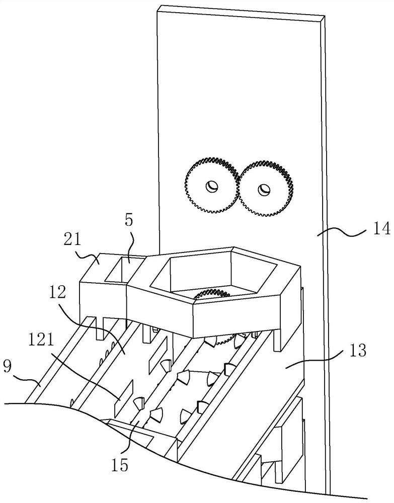
[0047] (3) Weld the end plates to both ends of the I-beam, and install the motor and the biaxial stirring paddle;

[0048] (4) Fill the reserved groove with soil, and then fix the first joint body and the second joint body on the first board and the second board by screws;

[0049] (5) Repeat the above steps until a self-embedded retaining wall of the desired height is formed.


PUM


Abstract

The invention relates to a self-embedded type retaining wall and a construction method thereof. The self-embedded type retaining wall comprises a bearing frame, first splicing bodies and second splicing bodies. The bearing frame is in threaded connection to an old wall, the first splicing bodies are inserted into the bearing frame and face a water side, and the second splicing bodies face a filling side. Preformed grooves are formed in the bearing frame in the length direction, closed ring bodies opposite to the preformed grooves are defined by the first splicing bodies and the second splicingbodies, planting grooves communicating with the preformed grooves are formed in the front ends of the first splicing bodies, water flow holes are reserved in the bearing frame, the bearing frame is fixed to the old wall, it is guaranteed that the first splicing bodies and the second splicing bodies are located on the same reference surface, then the preformed grooves are filled with soil, the first splicing bodies and the second splicing bodies are mounted on the bearing frame, the closed ring bodies are defined by the first splicing bodies and the second splicing bodies, green plants are planted in the planting grooves, meanwhile, and water in a riverway flows into the preformed grooves through the water flow holes to soak the soil. The self-embedded type retaining wall is convenient toconstruct, high in mounting efficiency and high in consistency.

Description

technical field [0001] The invention relates to the technical field of slope protection, in particular to a self-embedded retaining wall. Background technique [0002] Due to historical reasons, many river embankments have been built with traditional retaining walls, mainly masonry, concrete, reinforced concrete retaining walls, etc. When these traditional forms of hard retaining walls are applied to river regulation, most of them only pay attention to the flood and drainage functions of the river, but pay less attention to the ecological environment. With the development of urban economy and social progress, people pay more and more attention to the ecological environment. The construction of urban rivers should not only make embankments play the role of water conservancy projects, but also integrate urban landscape, ecological environmental protection, architectural art and other contents into a unique linear landscape in the city. [0003] The self-embedded retaining wa...

Claims


Application Information

Patent Timeline
Patent Type & Authority Patents(China)
IPC IPC(8): E02B3/12E02D29/02A01G9/02
CPCA01G9/02E02B3/12E02D29/02
Inventor 黄波邱学山
Owner 河海大学设计研究院有限公司
Learn More