A slider bonding process equipment and bonding method

A process equipment and bonding technology, applied in mechanical equipment, connecting components, etc., can solve the problems of uneven thickness, low adaptability and versatility, and high production cost, achieve good adaptability and versatility, and avoid copper grooves. The effect of uneven thickness and uniform force

Active Publication Date: 2021-01-08
BEIJING HANGXING MACHINERY MFG CO LTD
View PDF6 Cites 0 Cited by
  • Summary
  • Abstract
  • Description
  • Claims
  • Application Information

AI Technical Summary

Problems solved by technology

[0003] In the current traditional scheme, a single bonding device can only adapt to the bonding work of a single-sized slider, which is not high in adaptability and versatility, and the production cost is high
Especially in the case of heavy production tasks, a large number of sliders on a certain product need to be bonded. Due to the non-uniform size, the traditional bonding method cannot achieve adaptability and versatility, and cannot guarantee the bonding time. The copper grooves on each surface are evenly stressed, resulting in uneven thickness of the copper grooves after bonding and cannot be used

Method used


Image

  • A slider bonding process equipment and bonding method
  • A slider bonding process equipment and bonding method
  • A slider bonding process equipment and bonding method

Examples


Embodiment 1

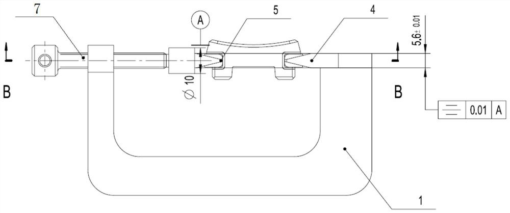
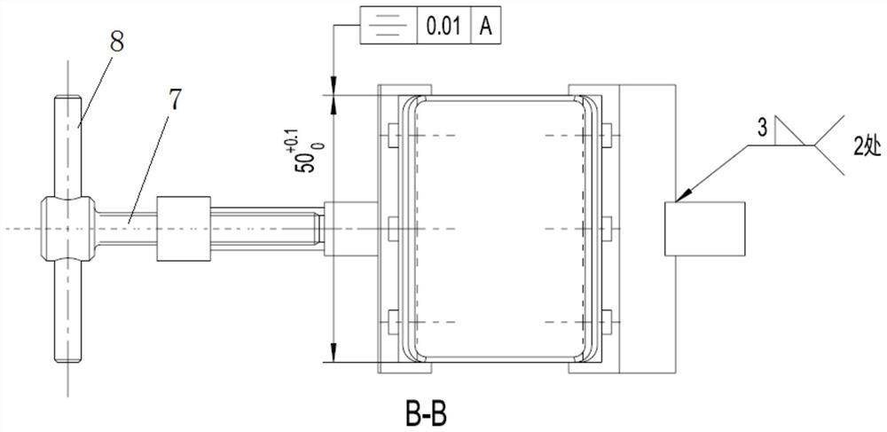
[0041] Such as Figure 1-9 As shown, the slider bonding process equipment described in this embodiment may specifically include: a bow clamp 1, a first jacking block 2, a second jacking block 3, a third jacking block 4, a fourth jacking block 5, and a positioning pin 6 , movable handle compression screw 7 and movable handle 8.

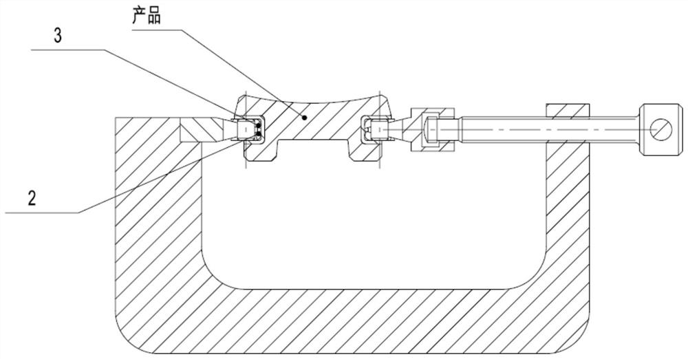
[0042] In this embodiment, one end of the bow clip 1 is provided with a threaded hole, and the movable handle pressing screw 7 is installed on the bow clip 1 through the threaded hole; the other end of the bow clip 1 is provided with a groove, and the second top block 3 Installed in the groove of the bow clip 1, and welded to shape. The movable handle compression screw 7 is provided with threads and mounting holes, and the fourth top block 5 is threadedly connected with the movable handle compression screw 7; the movable handle 8 passes through the mounting hole and is connected with the movable handle compression screw 7. The first jacking block 2 a...

Embodiment 2

[0052] The invention also discloses a bonding method, which includes: connecting the fourth top block 5 with one end of the bow clamp 1 by pressing the screw 7 through the movable handle; wherein, one end of the bow clamp 1 is provided with a threaded hole, and the movable handle presses Screw 7 is provided with screw thread and installation hole, movable handle pressing screw 7 is installed on the bow clamp 1 through the threaded hole on the bow clamp 1, the fourth jacking block 5 compresses the screw thread on the screw 7 and the movable handle through the movable handle The compression screw 7 is connected; the movable handle 8 is connected with the movable handle compression screw 7 through the mounting hole on the movable handle compression screw 7; the second top block 3 is installed in the groove at the other end of the bow clip 1, and Forming with welding; through the positioning pin 6, the first jacking block 2 and the second jacking block 3 are positioned and connecte...


PUM


Abstract

The invention discloses sliding block bonding process equipment and a bonding method. The equipment comprises an arch clam, a first ejection block, a second ejection block, a third ejection block, a fourth ejection block, a positioning pin, a movable handle compression screw and a movable handle; a threaded hole is formed in one end of the arch clamp, and the movable handle compression screw is installed on the arch clamp through the threaded hole; a groove is formed in the other end of the arch clamp, the second ejection block is installed in the groove of the arch clamp and is welded and formed; threads and a mounting hole are formed in the movable handle compression screw, and the fourth ejection block is connected to the movable handle compression screw through the threads; the movablehandle penetrates through the mounting hole to be connected to the movable handle compression screw; the first ejection block and the second ejection block are located and connected through the positioning pin; and the third ejection block is welded to the other end of the arch clamp and is arranged in parallel with the fourth ejection block. According to the bonding process equipment and the bonding method, the equipment is located positioned through the arch clamp and the ejection blocks, and the movable handle compression screw is used for applying force and clamping, so that a product isbonded and fixedly formed with a product copper groove.

Description

technical field [0001] The invention belongs to the field of bonding technology, and in particular relates to a slider bonding process equipment and a bonding method. Background technique [0002] The slider of a certain product needs to be bonded and fixed with copper grooves. [0003] In the current traditional solution, a single bonding device can only be adapted to the bonding work of a slider of a single size, and the adaptability and versatility are not high, and the production cost is relatively high. Especially in the case of heavy production tasks, a large number of sliders on a certain product need to be bonded. Due to the non-uniform size, the traditional bonding method cannot achieve adaptability and versatility, and cannot guarantee the bonding time. The copper grooves on each surface are evenly stressed, resulting in uneven thickness of the copper grooves after bonding and making them unusable. Contents of the invention [0004] The technical problem solved...

Claims


Application Information

Patent Timeline
Patent Type & Authority Patents(China)
IPC IPC(8): F16B11/00
CPCF16B11/00
Inventor 邓昊一秦英王希宇杨海峰
Owner BEIJING HANGXING MACHINERY MFG CO LTD
Why Eureka
Try Eureka