
Safe ignition circuit with short-circuit safety function

A technology of ignition circuit and insurance function, which is applied to weapon accessories, fuzes, offensive equipment, etc., can solve the problems of increasing system complexity and failure rate, complex structure of mechanical short-circuit switch, low reliability, etc., and achieves high engineering practical value and Cost advantage, realizing timing insurance and safe ignition, fast switching effect

Pending Publication Date: 2019-03-15
ZHONGBEI UNIV
View PDF0 Cites 4 Cited by
  • Summary
  • Abstract
  • Description
  • Claims
  • Application Information

AI Technical Summary

Problems solved by technology

For example, the resistance of the explosive wire electric detonator is on the order of mΩ, and the resistance of the bridge wire electric detonator is on the order of Ω. In order to effectively bypass the electric energy that may be added to the electric detonator in the short circuit state, spring pins and reeds are often used in domestic weapon systems. The mechanical short-circuit switch is connected in parallel on the two pins of the electric detonator. The mechanical short-circuit switch has the disadvantages of complex structure, high cost and low reliability. The pure electronic ignition circuit needs to cooperate with the mechanical short-circuit switch to form the ignition device to work, which increases the complexity of the system. degree and failure rate

Method used


Image

  • Safe ignition circuit with short-circuit safety function
  • Safe ignition circuit with short-circuit safety function
  • Safe ignition circuit with short-circuit safety function

Examples


Embodiment Construction

[0020] The following will clearly and completely describe the technical solutions in the embodiments of the present invention with reference to the accompanying drawings in the embodiments of the present invention. Obviously, the described embodiments are only some, not all, embodiments of the present invention. Based on the embodiments of the present invention, all other embodiments obtained by persons of ordinary skill in the art without making creative efforts belong to the protection scope of the present invention.

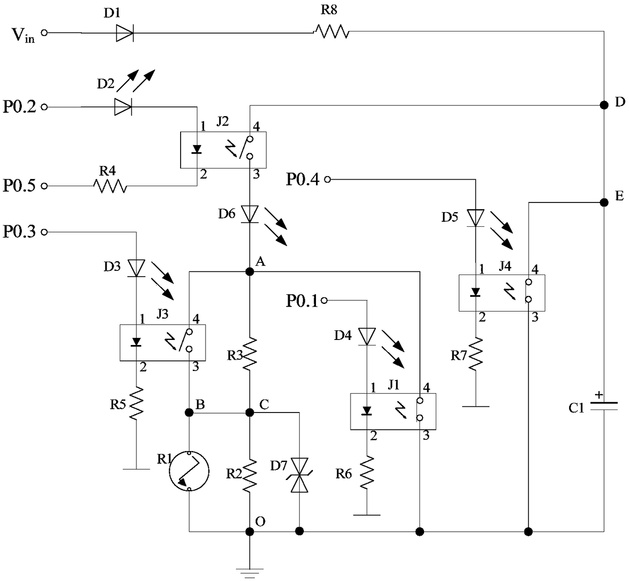
[0021] The normally open photorelay is used as the ignition switch, and its two input side control pins are connected to the single-chip microcomputer, and the single-chip microcomputer outputs 1 and 0 at the same time as the ignition switch from the off state to the two-way control signal to control the ignition circuit. Through communication, it can realize the effective and safe control of the ignition of electric pyrotechnics and improve the anti-interferen...


PUM


Abstract

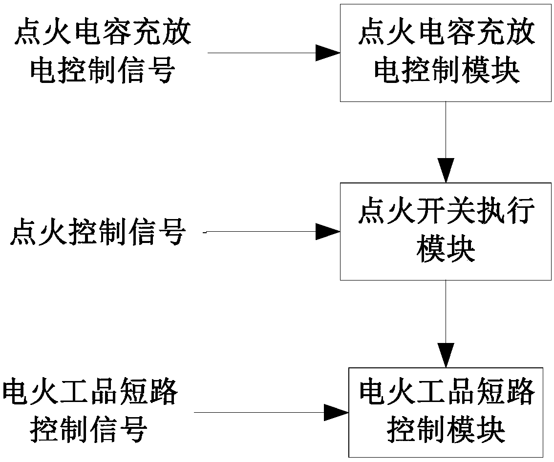
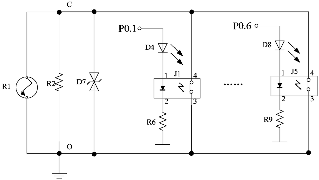
The invention discloses a safe ignition circuit with a short-circuit safety function, and relates to the technical field of safety control over conventional ammunition electronic fuses, missile rocketprojectiles, electric detonators in the industrial and mining field and other electric initiating explosive devices, and electronic circuits. By adding voltage-dividing, shunting, discharge and anti-interference elements in the ignition circuit of an electric initiating explosive device and designing a logic circuit based on low-cost normally closed and normally open optical relays, the ignitioncircuit has the functions of controlling the charging and discharging of an ignition capacitor, controlling the safety of an ignition switch, controlling the short circuit of the electric initiating explosive device, removing and restoring insurance and the like, so that the output side of the optical relay can meet the ignition and detonation conditions of the electric initiating explosive deviceonly by acting according to a time sequence according to a control signal, and the electronic circuit replaces a mechanical short circuit switch, thereby simplifying and reducing the structure of anignition device, preventing the accidental ignition of the electric initiating explosive device and finally forming the high-performance electric control safe ignition circuit with light weight, smallsize, reliable safety and quick unlocking.

Description

technical field [0001] The invention relates to the field of safety control technology and electronic circuit technology of conventional ammunition electronic fuzes, missile rockets, electric detonators in the industrial and mining fields and other electrical explosives, specifically a safety ignition circuit with a short-circuit insurance function for electrical explosives. Background technique [0002] The ignition circuit of conventional ammunition electronic fuze detonation control circuit, missile rocket engine ignition device, electric detonator in industrial and mining fields, electric ignition tube and other electric pyrotechnic products is generally composed of ignition switch, electric pyrotechnic product and energy storage capacitor (ignition capacitor). When working, the ignition circuit is under the action of the control signal to turn on the ignition switch, and the energy storage capacitor releases the stored electric energy to the electric pyrotechnic product ...

Claims


Application Information

Patent Timeline
Patent Type & Authority Applications(China)
IPC IPC(8): F42C15/40F42C19/12
CPCF42C15/40F42C19/12
Inventor 李波袁泽慧李世中张亚
Owner ZHONGBEI UNIV
Learn More