Chromatographic analysis method

A chromatographic analysis and chromatogram technology, applied in the field of fluid detection, can solve problems such as extended flow changes, state failures, valves prone to drift, etc., and achieve the effect of simplifying complexity

Inactive Publication Date: 2019-03-15
FOCUSED PHOTONICS
View PDF9 Cites 2 Cited by
  • Summary
  • Abstract
  • Description
  • Claims
  • Application Information

AI Technical Summary

Problems solved by technology

This scheme can be precisely controlled when the air flow changes little, but the valve often causes the air flow to produce reciprocating disturbance changes during the movement process in response to the flow change, which amplifies and prolongs the original flow change and makes the chromatogram baseline changes
This is also a problem when EPC or EFC is used. At the same time, the valve is prone to drift and state failure during frequent movements, and the cost is relatively high during use.

Method used


Image

  • Chromatographic analysis method

Examples


Embodiment 1

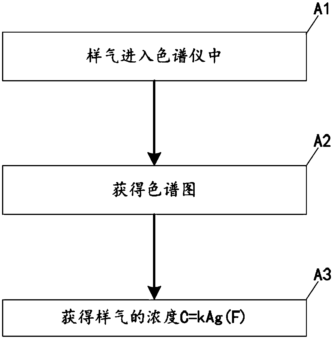
[0017] figure 1 The flow chart of the chromatographic analysis method in the embodiment of the present invention is schematically provided, such as figure 1 As shown, the chromatographic analysis method comprises the following steps:

[0018] (A1) The sample gas enters the chromatograph;

[0019] (A2) obtain a chromatogram;

[0020] (A3) Obtain the concentration of the sample gas C=k·A·g(F), k is the coefficient, A is the area or peak height of the characteristic peak, and g(F) is the peak area or peak height correction function related to the flow rate;

[0021] The way to obtain the correction function g(F) is:

[0022] Record the characteristic peak area or peak height corresponding to different flow rates: F i …A i , i∈N and i≥2;

[0023] fit out Such as by polynomial fitting.

Embodiment 2

[0025] An application example of the chromatographic analysis method according to Example 1 of the present invention.

[0026] In this application example, the chromatographic analysis method includes the following steps:

[0027] (A0) Record the characteristic peak area or peak height corresponding to different flow rates: F i …A i , i∈N and i≥2;

[0028] Fitted by polynomial

[0029] (A1) The sample gas enters the chromatograph;

[0030] Adjust the sampling frequency of the chromatograph to satisfy: f(0) is the initial frequency of sampling, v(t) is the real-time velocity of the sample gas during sampling, and v(0) is the initial velocity of the sample gas during sampling;

[0031] (A2) obtain a chromatogram;

[0032] (A3) Obtain the concentration of the sample gas C=k·A·g(F), k is the coefficient, A is the area or peak height of the characteristic peak, and g(F) is the correction function of the peak area or peak height related to the flow rate.

Embodiment 3

[0034] An application example of the chromatographic analysis method according to Example 1 of the present invention.

[0035] In this application example, the chromatographic analysis method includes the following steps:

[0036] (A0) Record the characteristic peak area or peak height corresponding to different flow rates: F i …A i , i∈N and i≥2;

[0037] Fitted by polynomial

[0038] (A1) The sample gas enters the chromatograph;

[0039] (A2) obtain a chromatogram;

[0040] Process the chromatogram in the following way:

[0041] Adjust the sampling frequency of the chromatograph to satisfy: f(0) is the initial frequency of sampling, v(t) is the real-time velocity of the sample gas during sampling, and v(0) is the initial velocity of the sample gas during sampling;

[0042] processing the chromatogram with the adjusted sampling frequency;

[0043] (A3) Obtain the concentration of the sample gas C=k·A·g(F), k is the coefficient, A is the area or peak height of the c...


PUM


Abstract

The invention provides a chromatographic analysis method. The chromatographic analysis method comprises the steps as follows: (A1) sample gas enters a chromatograph; (A2) a chromatogram is obtained; (A3) the concentration C=k.A.g(F) of the sample gas is obtained, wherein k is a coefficient, A is the area or height of a characteristic peak, and g(F) is a peak area or peak height modified function related to flow. The chromatographic analysis method has the advantages that the flow is not required to be controlled accurately and the like.

Description

technical field [0001] The present invention relates to fluid detection, in particular to a gas chromatographic analysis method. Background technique [0002] Gas chromatographic analyzers are widely used analytical instruments. In chromatographic analysis instruments, there are very high requirements for the flow rate of the measured gas or carrier gas flowing through the chromatographic column, especially industrial online gas chromatography instruments that work continuously online. The flow rate not only affects the time sequence of injection valve switching in chromatography and the retention time of chromatographic peaks, but also affects the shape and area of ​​chromatographic peaks if the flow rate is unstable, which directly affects the accuracy of the measured concentration. [0003] Usually gas chromatographs are designed with the addition of pressure or flow control devices, as well as pressure balancing of different flow paths to keep the flow through the detect...

Claims


Application Information

Patent Timeline
Patent Type & Authority Applications(China)
IPC IPC(8): G01N30/02
CPCG01N30/02
Inventor 俞大海
Owner FOCUSED PHOTONICS
Why Eureka
Try Eureka