
Optic-thermal coupling environment ground simulation device and method for different orbit altitudes of space

A technology of orbital height and photothermal coupling, applied in teaching models, educational tools, instruments, etc., can solve the problems of high power, inconvenient use of solar simulators, and does not consider the distance and angle relationship between the target and the radiation block, etc., to improve the simulation The effect of precision

Active Publication Date: 2019-03-15
BEIJING AEROSPACE INST OF THE LONG MARCH VEHICLE
View PDF7 Cites 4 Cited by
  • Summary
  • Abstract
  • Description
  • Claims
  • Application Information

AI Technical Summary

Problems solved by technology

In the existing space environment simulation test, due to the high power of the solar simulator, it needs to be preheated when using it, and it cannot be quickly switched from the shadow to the sunlight irradiation state, and there is still heat radiation for a period of time after it is turned off, so it cannot be quickly switched To the shadow state, it is very inconvenient to use, and the background radiation simulator does not consider the influence of the orbit height on the radiation heat flow, that is, the distance and angle relationship between the target and the radiation block are not considered during the radiation heat flow simulation process, and it is usually impossible to simulate accurately Various light and heat coupling environments in different areas

Method used


Image

  • Optic-thermal coupling environment ground simulation device and method for different orbit altitudes of space
  • Optic-thermal coupling environment ground simulation device and method for different orbit altitudes of space
  • Optic-thermal coupling environment ground simulation device and method for different orbit altitudes of space

Examples


Embodiment Construction

[0064] In order to make the purpose, technical solutions and advantages of the embodiments of the present invention clearer, the technical solutions in the embodiments of the present invention will be clearly and completely described below in conjunction with the drawings in the embodiments of the present invention. Obviously, the described embodiments It is a part of embodiments of the present invention, but not all embodiments. Based on the embodiments of the present invention, all other embodiments obtained by persons of ordinary skill in the art without making creative efforts belong to the protection scope of the present invention.

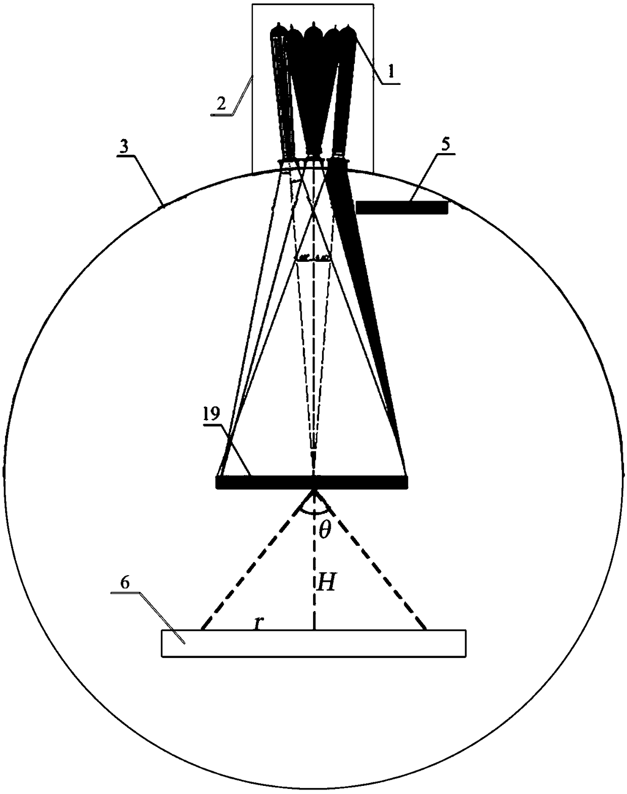
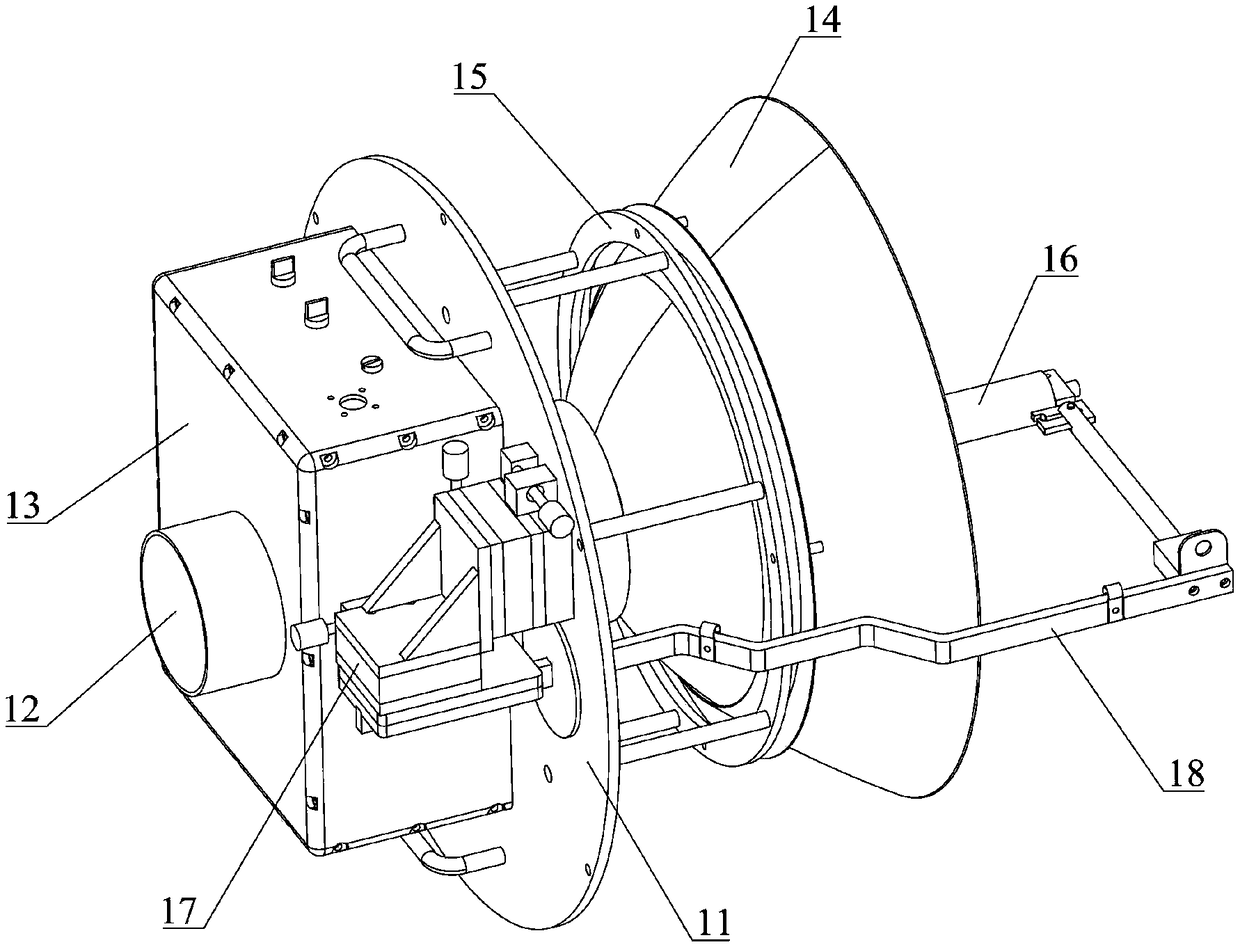
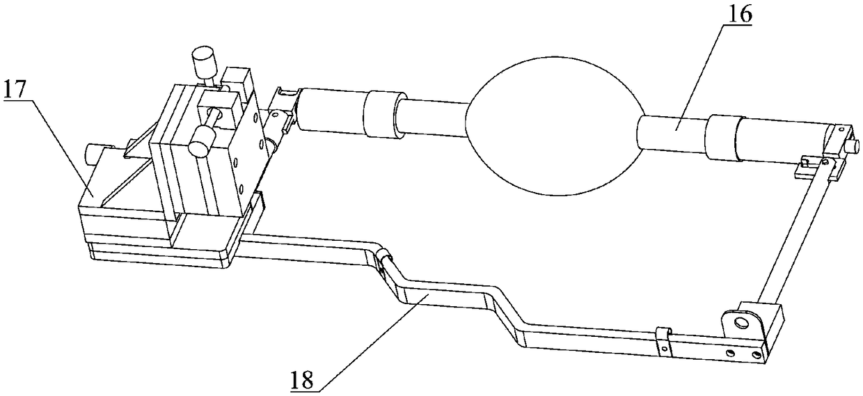
[0065] Such as figure 1 As shown, the embodiment of the present invention provides a ground simulation device for light-thermal coupling environment at different orbit heights in space, including: a solar simulator, a background radiation simulator 6 , a vacuum chamber 3 and a movable heat sink 5 . During use, the simulated spacecraft model ...


PUM


Abstract

The invention relates to an optic-thermal coupling environment ground simulation device for different orbit altitudes of space. The device comprises a solar simulator, a background radiation simulator, a vacuum chamber and a movable heat sink; the solar simulator comprises a multipath xenon lamp projection optical system and is arranged at the top of the vacuum chamber, multiple window mirrors arearranged at the top of the vacuum chamber, and all paths of system light beams irradiate the interior of the vacuum chamber after penetrating through the window mirrors; the movable hot sink is movably arranged in the vacuum chamber, multiple window mirrors can be shielded, refrigerating and cooling can be conducted by introducing liquid nitrogen, and quick switching between sunlight and shadow is achieved; the background radiation simulator is arranged inside the vacuum chamber and located below a spacecraft model; the background radiation simulator comprises multiple arc radiation blocks, apower source and a liquid nitrogen source, firstly, all the radiation blocks form annular areas with different radii, and all the annular areas with different radii are concentrically distributed toform the whole radiation face of the background radiation simulator. By means of the device, simulation of an optic-thermal coupling environment under different orbit altitudes and different radiationstates can be achieved.

Description

technical field [0001] The invention relates to the field of space environment ground simulation technology, in particular to a ground simulation device and method for light-thermal coupling environment at different orbital heights in space. Background technique [0002] The space environment at different orbital heights presents different photothermal coupling environments due to the different conditions of light radiation and heat radiation. In the existing space environment simulation test, due to the high power of the solar simulator, it needs to be preheated when using it, and it cannot be quickly switched from the shadow to the sunlight irradiation state, and there is still heat radiation for a period of time after it is turned off, so it cannot be quickly switched To the shadow state, it is very inconvenient to use, and the background radiation simulator does not consider the influence of the orbit height on the radiation heat flow, that is, the distance and angle rel...

Claims


Application Information

Patent Timeline
IPC IPC(8): G09B25/00
Inventor 孟刚南华李亚男薛莲周岩范小礼邓蓉白文浩刘得成赵民刘鑫
Owner BEIJING AEROSPACE INST OF THE LONG MARCH VEHICLE
Learn More