
Illuminating display with cascading double-goose-winged clearance tip-shaped cathode slope-wave hybrid line gated structure

A light-emitting display and hybrid line technology, which is applied in the direction of cathode ray tube/electron beam tube, image/graphic display tube, discharge tube, etc., can solve the problem that the electronic current of the light-emitting display cannot be effectively improved, the electric field intensity cannot be formed, and the light-emitting display cannot be formed. Electron current etc.

Active Publication Date: 2019-03-15
JINLING INST OF TECH
View PDF5 Cites 4 Cited by
  • Summary
  • Abstract
  • Description
  • Claims
  • Application Information

AI Technical Summary

Problems solved by technology

First, limited by the structure of the display and the manufacturing process of the display, the production area of ​​the carbon nanotube cathode is very small, which makes it impossible to effectively increase the electronic current of the light-emitting display because there are not enough carbon nanotubes to provide a large amount of electrons for the display. It is impossible to further improve the luminous brightness of luminous displays.
Second, in the light-emitting displays produced, the emission efficiency of carbon nanotubes is relatively low
After applying an appropriate gate voltage, some carbon nanotubes can emit electrons, but the number of emitted electrons is not much, and some carbon nanotubes do not emit electrons at all, and there are not enough carbon nanotubes for electron emission. Emission, light-emitting display is unable to form an effective electronic current
Third, the control ability of the gate electrode to the carbon nanotube cathode is very weak, and even in many cases, the gate electrode loses the control performance of the application for the carbon nanotube cathode. The surface of the cathode of the tube cannot form a strong electric field at all.

Method used


Image

  • Illuminating display with cascading double-goose-winged clearance tip-shaped cathode slope-wave hybrid line gated structure
  • Illuminating display with cascading double-goose-winged clearance tip-shaped cathode slope-wave hybrid line gated structure
  • Illuminating display with cascading double-goose-winged clearance tip-shaped cathode slope-wave hybrid line gated structure

Examples


Embodiment Construction

[0051] The present invention will be further described below in conjunction with the accompanying drawings and embodiments, but the present invention is not limited to this embodiment.

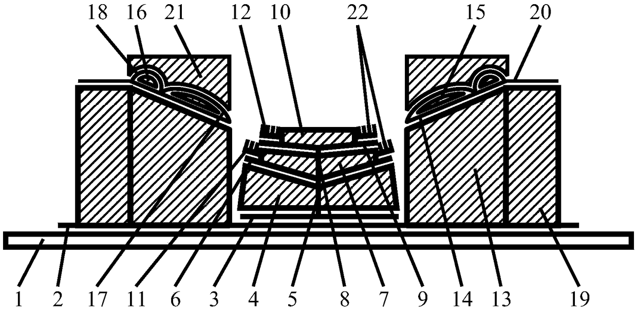
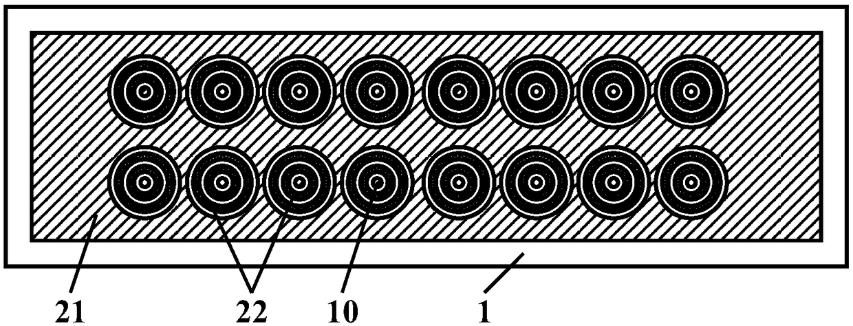
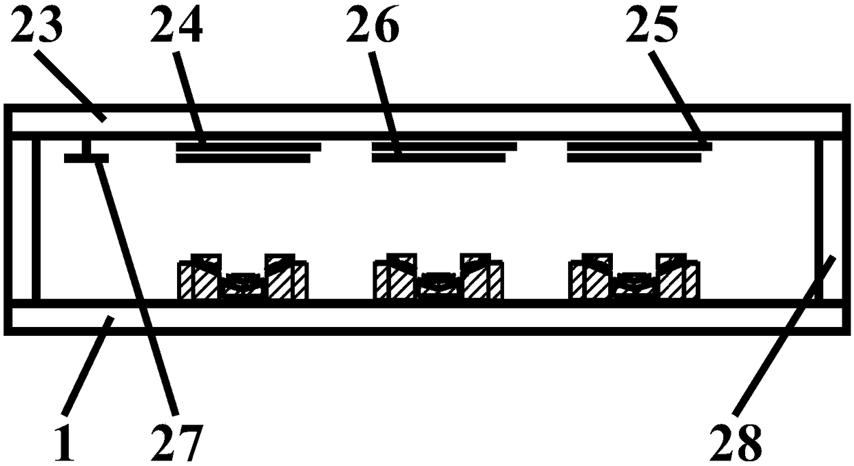
[0052] The light-emitting display with the stacked double goose-wing empty ring tip body cathode slope wave mixed line gating structure in this embodiment is as follows: figure 1 , figure 2 and image 3 As shown, it includes a vacuum enclosure and a getter 27 accessory components located in the vacuum enclosure. The vacuum enclosure is composed of a flat glass upper partition 23, a flat glass lower partition 1 and a rectangular glass strip 28; on the flat glass The separator 23 has a conductive film anode layer 24, an external line electric anode silver layer 25 and a thin luminescent layer 26, the conductive film anode layer 24 is connected to the external line electric anode silver layer 25, and the thin light emitting layer 26 is made on the conductive film anode On the layer 24; on the ...


PUM


Abstract

The invention discloses an illuminating display with a cascading double-goose-winged clearance tip-shaped cathode slope-wave hybrid line gated structure. The display comprises a vacuum enclosure and agetter accessory element located in the vacuum enclosure, wherein the vacuum enclosure is composed of a flat glass upper partition plate, a flat glass lower partition plate and a rectangular glass strip; a conductive film anode layer, an outer line electric anode silver layer and a thin luminescent layer are provided on the flat glass upper partition plate; the conductive film anode layer is connected to the outer line electric anode silver layer; the thin luminescent layer is formed on the conductive film anode layer; and the cascading double-goose-winged clearance tip-shaped cathode slope-wave hybrid line gated structure is arranged on the flat glass lower partition plate. The illuminating display provided by the invention has the advantages of diversified display illuminating colors, high display illuminating brightness, low manufacturing cost, and stable and reliable process.

Description

technical field [0001] The invention belongs to the fields of optoelectronic science and technology, nanometer science and technology, plane display technology, integrated circuit science and technology, vacuum science and technology and microelectronic science and technology, and relates to planar field emission luminescence The manufacture of the display specifically relates to the manufacture of a planar field emission luminescent display of a carbon nanotube cathode, in particular to a luminescent display with a stacked double goose-wing empty ring tip body cathode slope wave mixed line gate structure. Background technique [0002] Field emission light-emitting display is a new type of display device, which has been highly concerned by many researchers in recent years, and is known as an ideal display device for the next generation. In terms of cathodes of field emission luminescent displays, carbon nanotubes with good electron emission properties have been used as catho...

Claims


Application Information

Patent Timeline
IPC IPC(8): H01J31/12H01J29/04H01J9/20
CPCH01J9/20H01J29/04H01J31/126
Inventor 李玉魁武超崔栋
Owner JINLING INST OF TECH
Learn More