washing machine drive

A technology for driving devices and washing machines, applied to electromechanical devices, washing devices, and other washing machines, etc., can solve the problems of increasing the number of parts and achieve the effects of reducing wear, simplifying structure, and simplifying structure

Active Publication Date: 2021-04-30
NEW MOTECH
View PDF7 Cites 0 Cited by
  • Summary
  • Abstract
  • Description
  • Claims
  • Application Information

AI Technical Summary

Problems solved by technology

[0007] However, although the brake lever according to prior art 2 has a simple structure, a pressure lever for converting the rotation direction of the brake lever into the operation direction of the clutch lever should be applied, which leads to an increase in the number of parts

Method used


Image

  • washing machine drive
  • washing machine drive
  • washing machine drive

Examples


Embodiment Construction

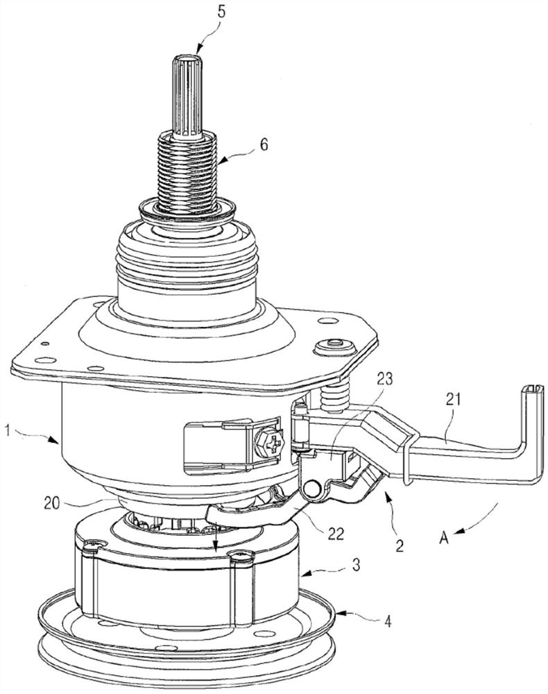
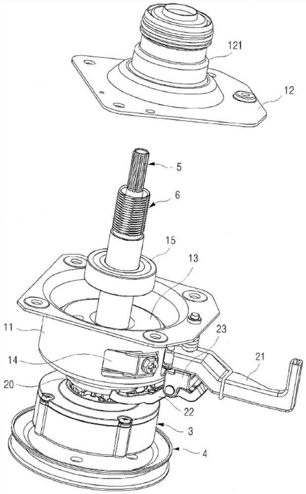
[0040] figure 1 It is a perspective view showing the driving device of the washing machine of the present invention, figure 2 It is an exploded perspective view showing the clutch main body 1 of the driving device of the washing machine of the present invention. Such as figure 1 and figure 2 As shown, the driving device for a washing machine according to the present invention includes a clutch main body 1 , a clutch operating unit 2 , a speed reducer 3 , a rotation driving device 4 , a washing shaft 5 and a dehydration shaft 6 .

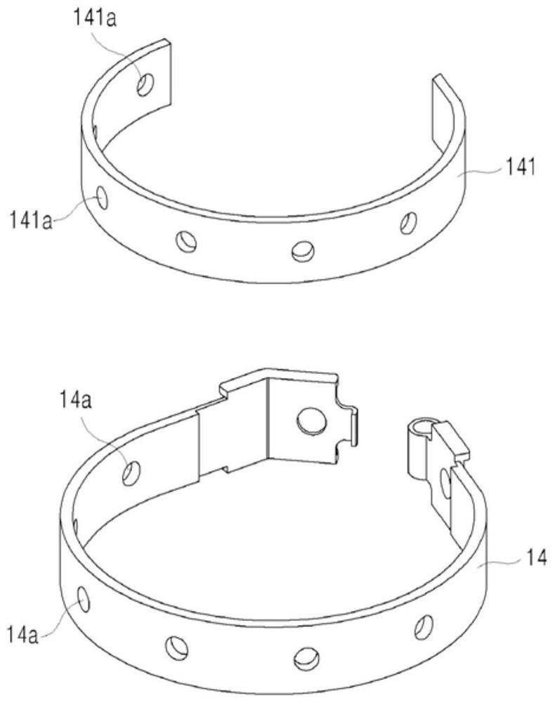
[0041] The clutch main body 1 includes a bottom case 11 and a top case 12 , and a brake drum 13 is located in a space inside the bottom case 11 . The brake drum 13 prohibits or stops the rotation of the spin shaft 6 when the brake band is pulled by the operation of the brake lever 21 . According to the present invention, since the speed reducer 3 is located outside the clutch body 1 and separated from the brake drum 13, the structure of the bra...


PUM


Abstract

The driving device for the washing machine according to the present invention includes: a clutch main body 1, in which a brake drum 13 is located; a clutch operating unit 2, which is installed on one side of the clutch main body 1, and the clutch operating unit includes a brake lever 21 and the clutch lever 22 that rotates together when the brake lever 21 is operated; the clutch coupler 20 at the bottom of the clutch body 1, the clutch link 22 moves the clutch coupler up and down; the speed reducer 3 at the bottom of the clutch coupler 20; Rotary driving device 4 at the bottom of the machine; washing shaft 5, wherein the pulsator is coupled to the top, and the washing shaft is coupled to the rotating driving device 4 and rotates together with the speed reducer 3; and a dehydration shaft 6, in which the washing shaft 5 is rotatably connected, And the washing tub is connected to the top of the washing tub, and the dehydration shaft passes through the center of the clutch body 1 and is rotatably connected to the center of the dehydration shaft 6, which is characterized in that the brake band 14 installed around the brake drum 13 passes through the brake Operation of the lever 21 presses around the brake drum 13 to perform a braking operation.

Description

technical field [0001] The invention relates to a driving device for a washing machine. More particularly, the present invention relates to a driving device for a washing machine which is simple in structure and capable of reducing manufacturing costs by introducing a new structure separating a brake drum located in a clutch housing from a speed reducer. Background technique [0002] Generally, washing machines are mainly classified into a pulsator type washing machine and a drum type washing machine. The drum type washing machine operates the drum type laundry tub by changing the rotation speed and torque, so that a washing mode and a dehydration mode can be applied. [0003] In the case of the pulsator type washing machine, the washing mode is performed by stopping rotation of the washing tub in a state where laundry is located in the washing tub and rotating a pulsator located in the washing tub to form water flow. In the dehydration mode, the washtub rotates so that la...

Claims


Application Information

Patent Timeline
Patent Type & Authority Patents(China)
IPC IPC(8): D06F37/40D06F37/12D06F37/24H02K7/102
CPCD06F37/40D06F37/12D06F37/24H02K7/102F16D65/065F16D65/78D06F37/304
Inventor 张贞喆朱成仲郑王圭李范硕
Owner NEW MOTECH
Why Eureka
Try Eureka