

Efficient heating device
A heating device, high-efficiency technology, applied in lighting and heating equipment, indirect heat exchangers, heat exchanger types, etc., can solve problems such as high operating temperature of radiators, achieve high levels of efficiency, increase power and overall efficiency, increase The effect of the overall heat exchange capacity
- Summary
- Abstract
- Description
- Claims
- Application Information
AI Technical Summary
Problems solved by technology
Method used
Image


Examples
Embodiment Construction
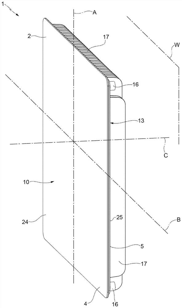
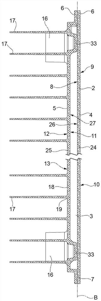
[0025] exist figure 1 and figure 2 In , a heating device of the hydronic (for example, hot water) type (for heating environments in buildings) is indicated as a whole by the reference numeral 1 .
[0026] The device 1 comprises a material made of thermally conductive material, such as (but not necessarily) a metallic material, in particular aluminum (the term also includes aluminum alloys, i.e. alloys containing aluminium) and aluminum obtained, for example, by die-casting (i.e. made of aluminum or The main body 2 is made of aluminum containing aluminum alloy produced by a die-casting process. It should be understood that the body 2 may be made of another material, provided it is suitable for conducting heat, such as ceramics, polymers, composites and others, and produced by other production processes, for example by extrusion.
[0027] Also refer to image 3 and Figure 4 , the body 2 is a hollow body and is provided with an inner cavity 3 (water cavity) in which a heati...
PUM
 Abstract
Description
Claims
Application Information