High efficiency heating device

A heating device, high-efficiency technology, applied in lighting and heating equipment, heat exchange equipment, heat exchanger types, etc., can solve problems such as high operating temperature of radiators, achieve high-level efficiency, increase overall efficiency, and increase power.

Active Publication Date: 2019-03-15
FONDITAL
View PDF7 Cites 0 Cited by
  • Summary
  • Abstract
  • Description
  • Claims
  • Application Information

AI Technical Summary

Problems solved by technology

[0006] However, the inventors of the invention in question have determined that with known solutions there is still room for significant improvement, especially in terms of specific power, and generally in terms of efficiency: even with good specific power, Known radiators generally require a relatively high operating temperature (the temperature of the water supplied to the radiator)

Method used


Image

  • High efficiency heating device
  • High efficiency heating device
  • High efficiency heating device

Examples


Embodiment Construction

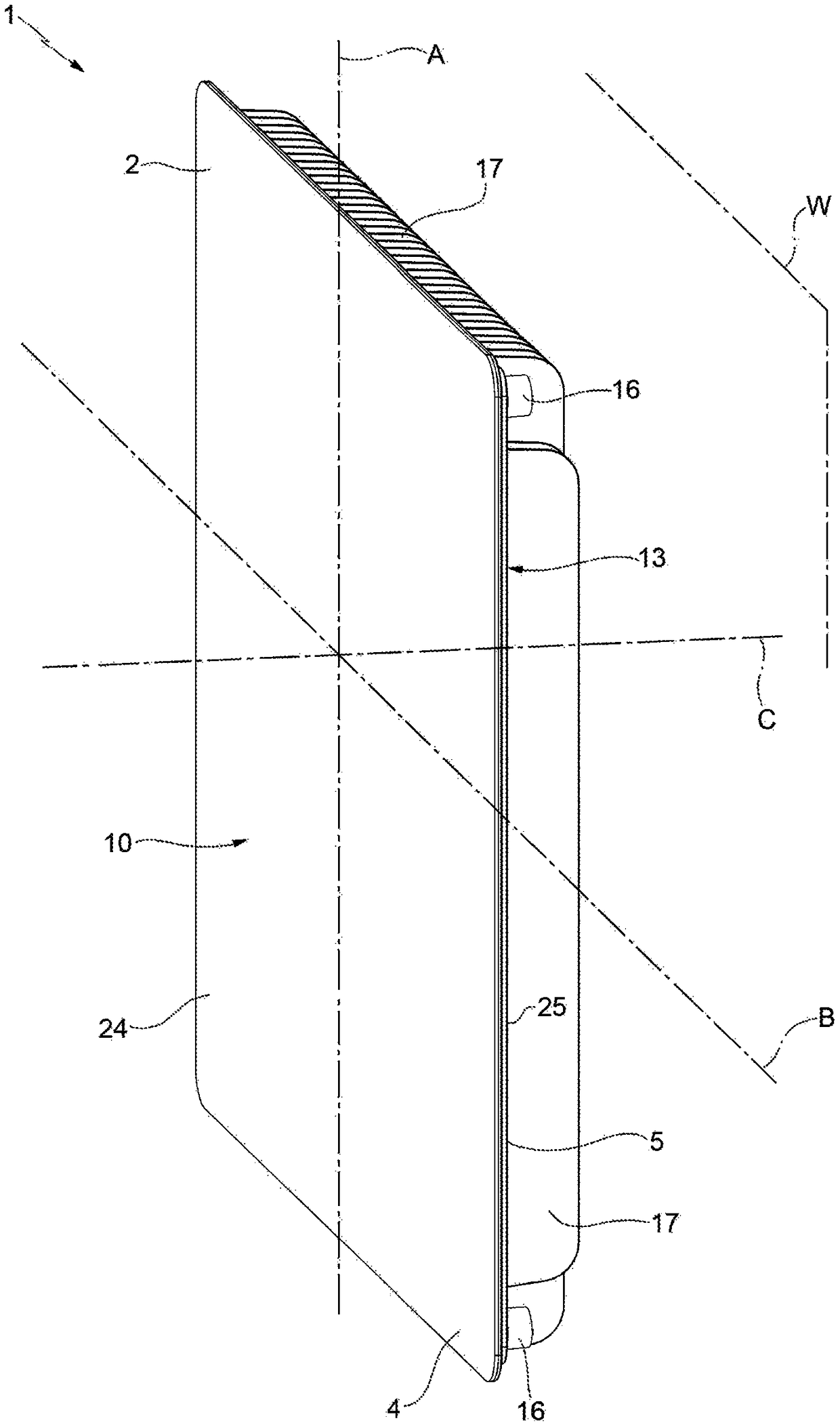
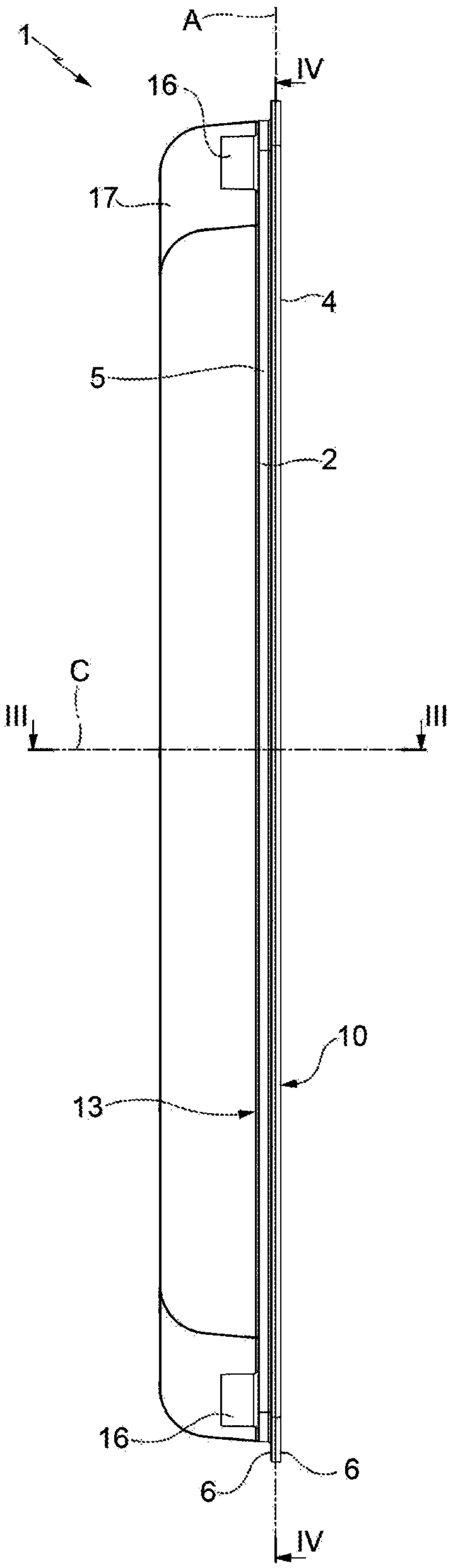
[0026] exist figure 1 and figure 2 In , a heating device of the hydronic (for example, hot water) type (for heating environments in buildings) is indicated as a whole by the reference numeral 1 .

[0027] The device 1 comprises a material made of thermally conductive material, such as (but not necessarily) a metallic material, in particular aluminum (the term also includes aluminum alloys, i.e. alloys containing aluminium) and aluminum obtained, for example, by die-casting (i.e. made of aluminum or The main body 2 is made of aluminum containing aluminum alloy produced by a die-casting process. It should be understood that the body 2 may be made of another material, provided it is suitable for conducting heat, such as ceramics, polymers, composites and others, and produced by other production processes, for example by extrusion.

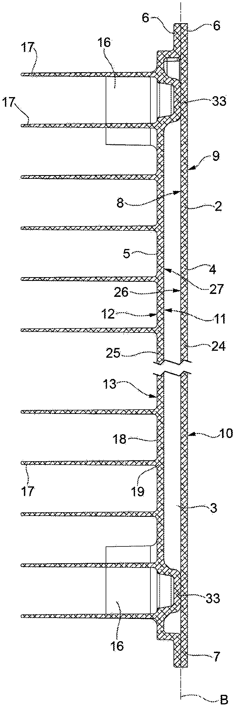
[0028] Also refer to image 3 and Figure 4 , the body 2 is a hollow body and is provided with an inner cavity 3 (water cavity) in which a heati...


PUM


Abstract

A high efficiency heating device (1) has a body (2) comprising an inner chamber (3) in which a heating liquid circulates; connections (16) communicating with the chamber (3) and extending from the body (2); and a front plate (4) having an outer face (9) facing in use the space to heat and defining a main front heat exchange surface (10) of the device (1); the chamber (3) is delimited by a pair ofmain walls (24, 25) facing each other and by a closed loop perimeter edge (7) connecting the main walls (24, 25); the chamber (3) has a ratio between surface and volume, expressed in dm2 and dm3, respectively, greater than or equal to 23.

Description

technical field [0001] The invention relates to a high-efficiency heating device. Background technique [0002] A common room heating system consists of radiators through which a heating liquid (usually hot water) circulates. [0003] The heat sinks used in these systems can be made from a variety of metallic materials and are usually formed from batteries of heat sink elements that are manufactured separately and then bonded together. [0004] A typical radiator element has a substantially tubular body provided with an internal cavity through which water flows (water cavity) and has hydraulic connections for connection to other similar radiator elements and / or hydraulic circuits and arrangements At opposite ends of the element; two opposing baffles extending from the water cavity along the centerline plane of the element, supporting the front and rear plates respectively; and a plurality of heat exchanging fins extending from the tubular body. [0005] Radiators comprisin...

Claims


Application Information

Patent Timeline
Patent Type & Authority Applications(China)
IPC IPC(8): F28F3/04F28D1/03F28D1/053
CPCF28D1/0308F28D1/05358F28D2021/0035F28F3/04Y02B30/00
Inventor 奥兰多·尼博利
Owner FONDITAL
Why Eureka
Try Eureka