
Fluorescence-lifetime imaging microscopy method having time-correlated single-photon counting, which method permits higher light intensities

A single photon counting, fluorescence lifetime technique, applied in the field of microscopy, which can solve the problems of cost realization, time resolution and signal utilization limitations

Active Publication Date: 2019-03-15
LEICA MICROSYSTEMS CMS GMBH
View PDF12 Cites 1 Cited by
  • Summary
  • Abstract
  • Description
  • Claims
  • Application Information

AI Technical Summary

Problems solved by technology

This approach can be implemented with relatively little equipment outlay, but is limited in terms of temporal resolution and signal utilization
Time-windowed methods working with CCD or CMOS cameras have similar disadvantages

Method used


Image

  • Fluorescence-lifetime imaging microscopy method having time-correlated single-photon counting, which method permits higher light intensities
  • Fluorescence-lifetime imaging microscopy method having time-correlated single-photon counting, which method permits higher light intensities
  • Fluorescence-lifetime imaging microscopy method having time-correlated single-photon counting, which method permits higher light intensities

Examples


Embodiment Construction

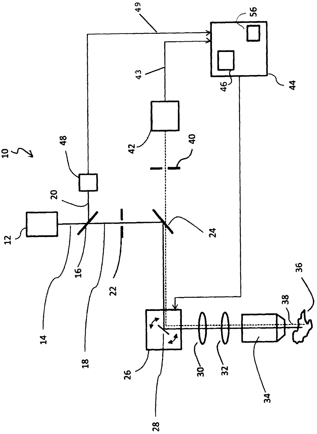
[0052] figure 1 A confocal scanning microscope 10 is shown, which is an embodiment of a microscope according to the invention.

[0053] The confocal scanning microscope 10 has a pulsed laser source 12 which is designed to emit light with periodic excitation light pulses. exist figure 1 Excitation light, denoted by 14 , enters a beam splitter 16 , which splits the excitation light 14 into a transmissive portion 18 and a reflective portion 20 .

[0054] Excitation light 18 transmitted through beam splitter 16 passes through excitation aperture 22 and is then reflected on dichroic beam splitter 24 in the direction of scanning unit 26 . Scanning unit 26 includes a gimbaled scanning mirror 28 which reflects excitation light 14 in the direction of scanning lens 30 . After passing through scan lens 30 and tube lens 32 , the excitation light enters microscope objective 34 , which directs excitation light 18 onto sample 36 .

[0055] In the region of the sample 36 irradiated with t...


PUM


Abstract

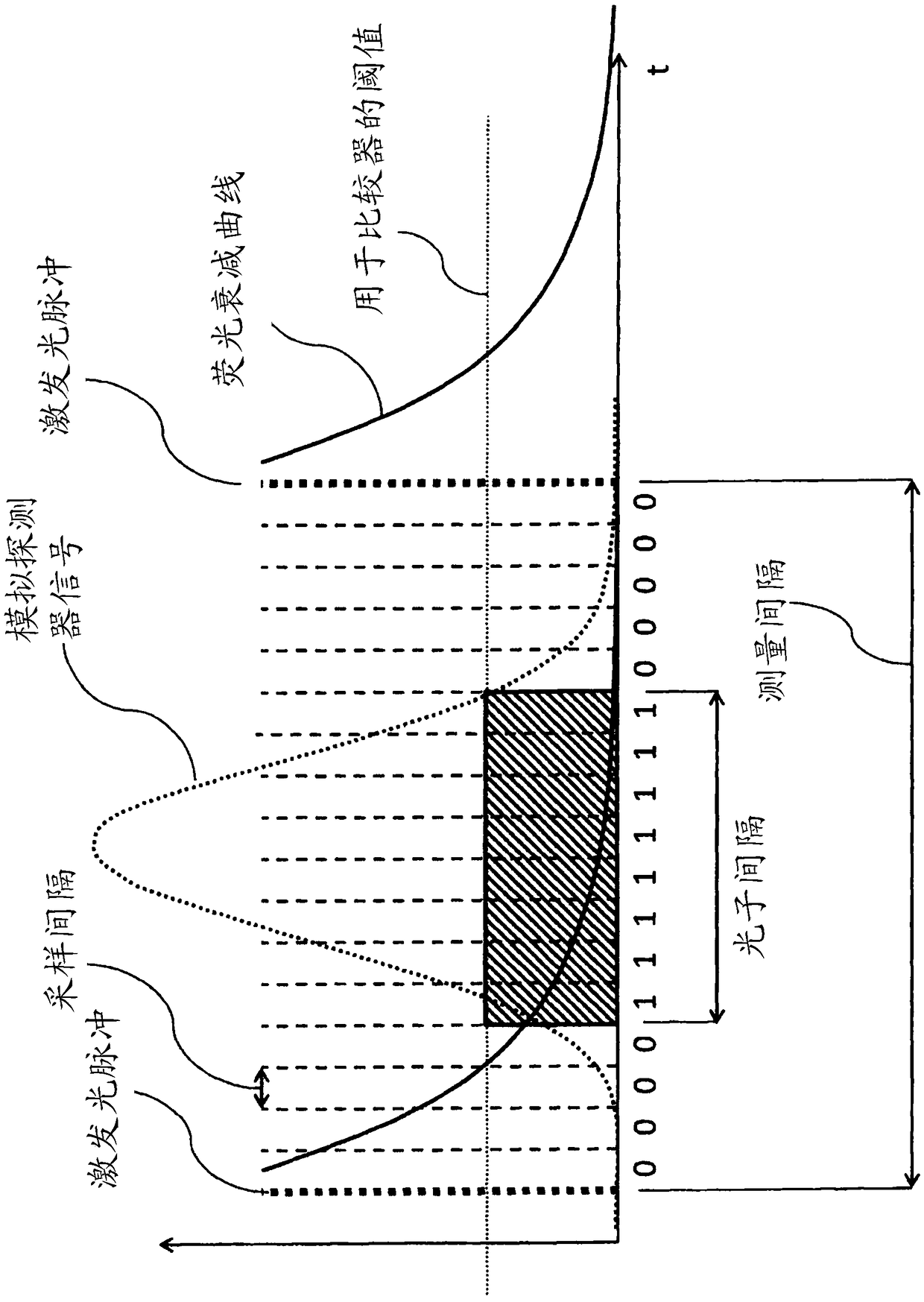
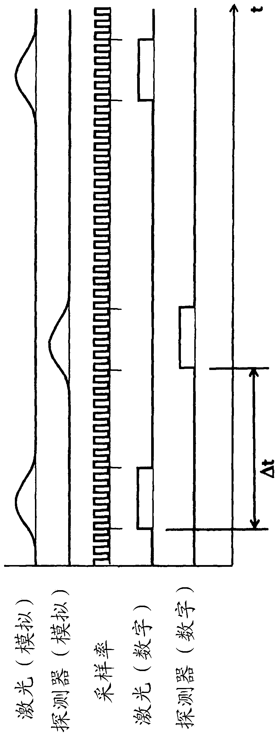
The invention relates to a fluorescence-lifetime imaging microscopy method having time-correlated single-photon counting, wherein a sample (36) is periodically excited with excitation light pulses toemit fluorescence photons by means of a pulsed light source (12), wherein a measurement interval is defined between each pair of consecutive excitation light pulses, the fluorescence photons are detected by means of a detector (42) and an analog detector signal representing the detected fluorescence photons is produced, detection times at which the fluorescence photons are detected by the detector(42) within the measurement intervals are determined on the basis of the detector signal, at least one value characterizing the fluorescence decay behavior is determined on the basis of the detectiontimes of the detected fluorescence photons, and imaging is performed on the basis of the characterizing value. The analog detector signal is sampled within each measurement interval in a plurality ofsampling intervals and is converted into a series of discrete signal values associated with the individual sampling intervals. On the basis of the series of discrete signal values that belongs to theassociated measurement interval, it is determined whether more than a predefined number of fluorescence photons has been detected within the measurement interval. This measurement interval is discarded for the determination of the characterizing value if more than said predefined number of fluorescence photons has been detected.

Description

technical field [0001] The invention relates to a method of fluorescence lifetime imaging microscopy using time-correlated single photon counting according to the preamble of claim 1 and a microscope for carrying out such a method according to the preamble of claim 16 . Background technique [0002] Fluorescence lifetime imaging microscopy, FLIM for short ("fluorescence lifetime imaging microscopy") is a fluorescence microscopy imaging method based on the measurement of different lifetimes of excited states of fluorescent molecules. With the aid of the measured lifetime, for example, properties of the environment of the fluorescent molecule can be inferred, such as pH value, temperature, ion concentration, FRET transfer (FRET=" Resonance Energy Transfer", fluorescence resonance energy transfer), etc. [0003] The fluorescence lifetime can be determined directly in the time domain (“time domain lifetime measurement”) or in an alternative method in the frequency range (“freq...

Claims


Application Information

Patent Timeline
IPC IPC(8): G01N21/64
CPCG01N21/6408G01N21/6458
Inventor V·塞弗里德B·威兹高斯基F·赫克特
Owner LEICA MICROSYSTEMS CMS GMBH
Learn More