A kind of high-efficiency chopping mechanism and chopping method

A tooth-chopping and high-efficiency technology, which is applied to the high-efficiency tooth-chopping mechanism and the field of tooth-chopping, can solve the problems of low working efficiency, low durability and high working pressure of the tooth-chopping machine, so as to improve the stability of use, the scope of application and the working pressure. high effect

Active Publication Date: 2020-03-17
中国兵器装备集团自动化研究所有限公司
View PDF5 Cites 0 Cited by
  • Summary
  • Abstract
  • Description
  • Claims
  • Application Information

AI Technical Summary

Problems solved by technology

[0003] The purpose of the present invention is to provide a high-efficiency tooth chopping mechanism and tooth chopping method to solve the problems in the prior art that the tooth chopping machine often needs to be stopped for recovery, low work efficiency, high working pressure and low durability, and realizes no need to stop Restoring and improving working efficiency, while improving the stability of use and prolonging the service life

Method used


Image

  • A kind of high-efficiency chopping mechanism and chopping method

Examples


Embodiment 1

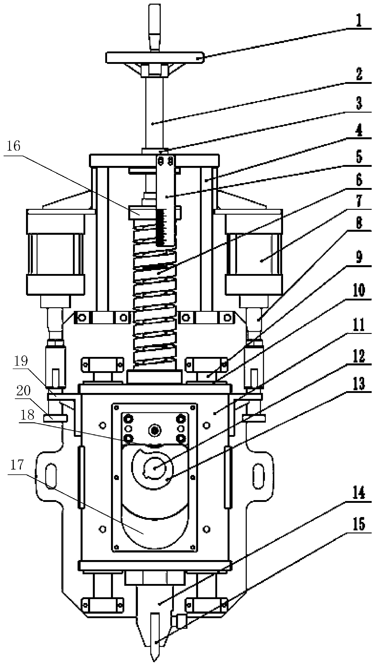
[0031] like figure 1 A kind of high-efficiency tooth chopping mechanism shown comprises a chopping knife 15, a clamping device 14 for clamping the chopping knife 15, and the chopping knife 15 is vertically downward, and the clamping device 14 and the chopping tooth ram 11 Fixedly connected, a bracket 4 is arranged above the tooth chopping ram 11, and a screw rod 2 passing through the bracket 4 is also included, a nut 3 is arranged on the top of the bracket 4, and the screw rod 2 passes through the nut 3, so The bottom end of the screw mandrel 2 is connected to the pressing plate 16 located in the bracket 4, a spring 6 is arranged between the top of the tooth chopping ram 11 and the bottom of the pressing plate 16, and a spring 6 is also included for driving the tooth chopping ram 11. The first linear drive mechanism for up and down motion.

Embodiment 2

[0033] On the basis of Example 1, such as figure 1 As shown, the first linear drive mechanism includes a through hole 17 opened inside the tooth chopping ram 11, a protrusion 18 protruding downward is provided on the inner top surface of the through hole 17, and a protrusion 18 is arranged below the protrusion 18 and located in the through hole. The cam 13 in the hole 17 is matched with the protrusion 18, and the cam 13 is driven by a motor to rotate. The output end of the motor drives the rotating shaft 12 to rotate through a shaft coupling, and the rotating shaft 12 is connected with the cam 13 by a flat key. It also includes a marking ruler 5 fixed on the bracket 4 , the said marking ruler 5 faces the top of the spring 6 , and the scale direction of the marking ruler 5 is parallel to the axis of the spring 6 . The hand wheel 1 is fixed on the top of the screw mandrel 2 .

Embodiment 3

[0035] On the basis of Embodiment 2, a second linear drive mechanism is also included, the driving end of the second linear drive mechanism is connected to the drawbar 8, and the driving direction of the second linear drive mechanism and the axis of the drawbar 8 are all parallel On the axis of the spring 6, the traction rod 8 is used to pull the chopping tooth ram 11 to move. The outer surface of the chopping tooth ram 11 is fixedly connected to the limit plate 19, the draw bar 8 passes through the limit plate 19 from top to bottom, and the bottom end of the draw bar 8 is fixed with a limit block 20, so The limiting block 20 cannot pass through the limiting plate 19. A sliding bearing 10 is arranged on the top of the tooth chopping ram 11 , and the sliding shaft 9 is inserted into the tooth chopping ram 11 through the sliding bearing 10 . The second linear drive mechanism is an air cylinder 7 fixed outside the bracket 4 .

[0036] A method for chopping teeth, comprising the...


PUM


Abstract

The invention discloses an efficient tooth cutting mechanism. The efficient tooth cutting mechanism comprises a cutting knife, a clamping device for clamping the cutting knife, a screw rod penetratingthrough a bracket, and a first straight line driving mechanism, wherein the cutting knife is vertically down, the clamping device is fixedly connected with a cutting tooth sliding sleeper, the bracket is arranged above the cutting tooth sliding sleeper, a nut is arranged on the top of the bracket, the screw rod penetrates through the nut, the bottom end of the screw rod is connected to a pressingplate located in the bracket, a spring is arranged between the top of the cutting tooth sliding sleeper and the bottom of the pressing plate, and the first straight line driving mechanism is used fordriving the upper and lower movement of the cutting tooth sliding sleeper. According to the efficient tooth cutting mechanism and a tooth cutting method, the problems that in the prior art, a tooth cutting machine often needs to stop to make recovery and has low work efficiency, meanwhile the working pressure is high, and durability is low are solved; and the purposes that stopping for making recovery is not needed, the work efficiency is improved, meanwhile the service stability is improved, and the service life is prolonged are realized.

Description

technical field [0001] The invention relates to the field of file processing, in particular to an efficient tooth chopping mechanism and a tooth chopping method. Background technique [0002] Chopping is a process used to make files. On the working surface of the steel file body made of steel rolled into various shapes of file blanks, numerous sharp edge lines are regularly chopped along the axial direction. The original file chopping teeth was manually chiseled with a small flat-mouthed chisel, and in modern times, a gear chopping machine is used for mechanical chopping. The file with chopped teeth is heat-treated and can be used after reaching the required hardness. There is a lot of noise when chopping teeth with a gear cutter. In the prior art, there are tooth chopping mechanisms that rely on pneumatic or hydraulic pressure as power. This type of tooth chopping mechanism is directly connected to the tooth chopping ram mechanism and the chopping knife by the cylinder o...

Claims


Application Information

Patent Timeline
Patent Type & Authority Patents(China)
IPC IPC(8): B23D73/06
CPCB23D73/06
Inventor 周晓华钟金龙曹亦盛赖文娟邓小燕
Owner 中国兵器装备集团自动化研究所有限公司
Why Eureka
Try Eureka