
Wheel speed sensor assembly equipment

A wheel speed sensor and assembly equipment technology, applied in other manufacturing equipment/tools, manufacturing tools, etc., can solve the problems of unqualified and unqualified product sorting, low production efficiency, and affecting processing accuracy

Active Publication Date: 2020-06-02
深圳市伊特祺电子科技有限公司
View PDF5 Cites 0 Cited by
  • Summary
  • Abstract
  • Description
  • Claims
  • Application Information

AI Technical Summary

Problems solved by technology

The shortcomings of the existing automobile wheel speed sensor production are: 1. The welding of the housing and the electronic counter, and the bending operation of the electronic counter are carried out separately, and the processing efficiency is low; 2. The loading and unloading of the housing and the electronic counter is slow, resulting in high production efficiency. Low; 3. The structure of the carrier holding the shell during processing is simple and cannot be accurately positioned. It is difficult to perform other operations on the shell in the carrier, which affects the accuracy of processing and leads to a low pass rate of the product; 4. Shell The connection with the electronic counter is of low firmness, which affects the qualified rate of the product; 5. When the shell is welded with the electronic counter, welding slag splashes easily damages the electronic counter, which affects the qualified rate of the product; Inspect the conditions that affect the product qualification rate, such as damaged electronic counters, that is, it is impossible to sort qualified and unqualified products, and the inspection needs to be followed by manual operations, which is time-consuming and laborious

Method used


Image

  • Wheel speed sensor assembly equipment
  • Wheel speed sensor assembly equipment
  • Wheel speed sensor assembly equipment

Examples


Embodiment Construction

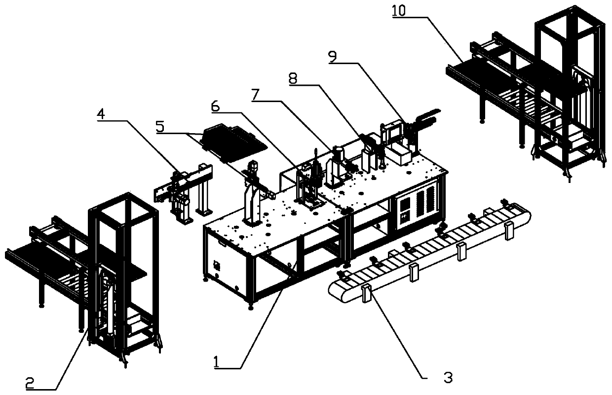
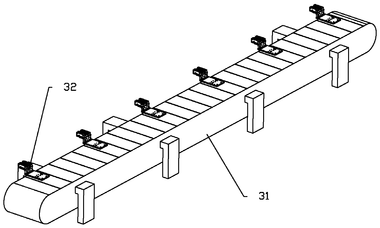
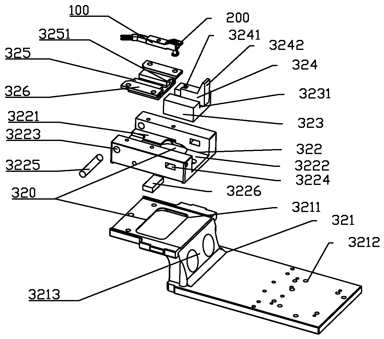
[0021] Such as figure 1 As shown, the wheel speed sensor assembly equipment includes frame 1, feeding device 2, circulation conveying line device 3, feeding manipulator device 4, electronic counter feeding device 5, hot-melt pressing device 6, welding device 7, folding Bending device 8, unloading manipulator device 9 and discharging device 10, feeding device 2 and discharging device 10 are respectively located on both sides of frame 1, feeding device 2 is connected with loading manipulator device 4, discharging device 10 is connected with The unloading manipulator device 9 is connected; the circular conveying line device 3, the feeding manipulator device 4, the electronic counter feeding device 5, the hot-melt pressing device 6, the welding device 7, the bending device 8, and the unloading manipulator device 9 are installed on the machine. On the frame 1; along the processing direction of the workpiece, the feeding manipulator device 4, the electronic counter feeding device 5,...


PUM


Abstract

The invention relates to the field of sensor production. A wheel speed sensor assembly equipment comprises a machine frame and a circulating conveying line device and a bending device, wherein the circulating conveying line device and the bending device are arranged on the machine frame, and the position of the circulating conveying line device corresponds to that of the bending device. The wheelspeed sensor assembly equipment has the advantages of accurate positioning and operation of carrier assemblies, convenient assembly and bending of electronic counters, high automation degree and highqualified rate of finished products.

Description

technical field [0001] The invention relates to the field of sensor production, in particular to equipment for the production of automobile wheel speed sensors. Background technique [0002] The wheel speed sensor is a sensor used to measure the speed of the car wheel. For modern cars, wheel speed information is essential, vehicle dynamic control system (VDC), automotive electronic stability program (ESP), anti-lock braking system ABS, automatic transmission control system, etc. need wheel speed information . The automobile wheel speed sensor is generally composed of a housing and an electronic counter. The housing is composed of a sensing head and a ring gear. The existing assembly method of the automobile wheel speed sensor is to weld the housing and the electronic counter together. After welding, the electronic The counter performs the bending operation. The shortcomings of the existing automobile wheel speed sensor production are: 1. The welding of the housing and the...

Claims


Application Information

Patent Timeline
Patent Type & Authority Patents(China)
IPC IPC(8): B23P23/06
CPCB23P23/06
Inventor 李青华
Owner 深圳市伊特祺电子科技有限公司
Learn More