
An elevator car position and speed detection system and its self-test method

A technology for detecting the position and speed of an elevator car, applied in the field of elevators, can solve the problems of high detection cost, inaccuracy, and complicated detection technology, and achieve the effects of high detection accuracy, simplified detection technology, and safe, stable and reliable system

Active Publication Date: 2020-07-17
HITACHI ELEVATOR CHINA
View PDF18 Cites 0 Cited by
  • Summary
  • Abstract
  • Description
  • Claims
  • Application Information

AI Technical Summary

Problems solved by technology

[0002] At present, the conventional detection method for the position of the elevator car is to calculate the actual rotation circumference of the traction sheave from the measurement signal of the rotary encoder on the host side, so as to convert the moving distance of the wire rope and the position and speed of the car. It is a traction-drag mechanical system, that is to say, the traction wheel and the wire rope are connected by friction transmission, there will be slippage between the traction wheel and the wire rope, and due to the change of gravity of the mechanical system, the change of the humidity extension of the wire rope, etc. The reason is that the position of the car calculated by the encoder on the host side is relatively inaccurate. Generally, it is necessary to install multiple position sensors in the hoistway to continuously correct the real position of the car. Therefore, it is necessary to use a variety of equipment for detection, and the detection technology is complicated. And the detection cost is high

Method used


Image

  • An elevator car position and speed detection system and its self-test method
  • An elevator car position and speed detection system and its self-test method

Examples


Embodiment Construction

[0024] The preferred embodiments of the present invention will be described below in conjunction with the accompanying drawings. It should be understood that the preferred embodiments described here are only used to illustrate and explain the present invention, and are not intended to limit the present invention.

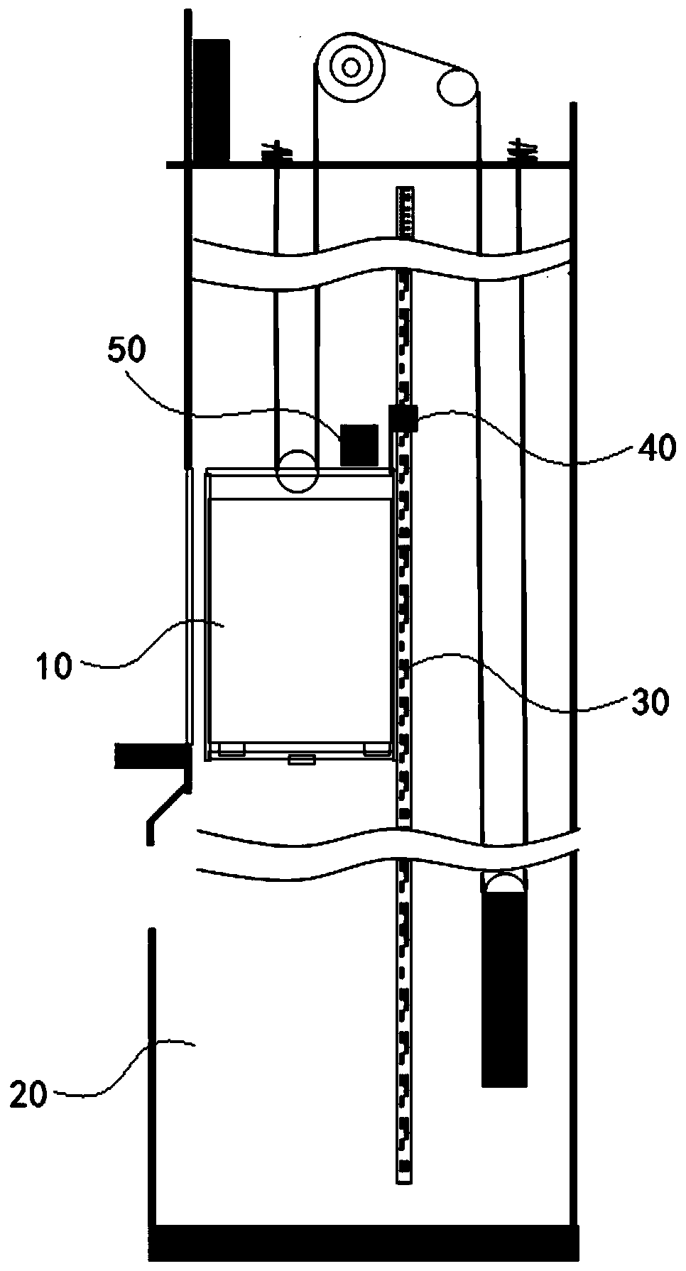
[0025] Such as figure 1 with figure 2 As shown, the present invention provides a position and speed detection system for the elevator car 10. The car 10 is located in the hoistway 20, and includes a scale 30 vertically arranged in the hoistway 20, and a device for collecting the information of the scale 30. A detection device 40, a controller 50 electrically connected to the detection device 40;

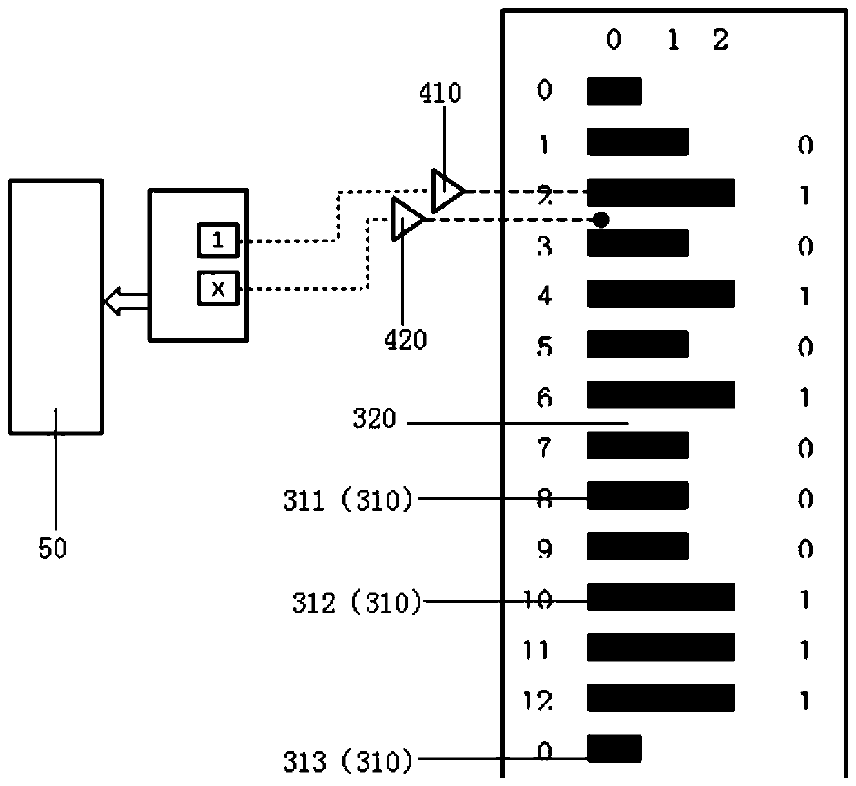
[0026] The scale 30 is provided with a column of markings arranged vertically, the markings include a first type of marking 310 and a second type of marking 320 arranged alternately along the length direction of the scale 30, the first type of marking 310 includes at le...


PUM


Abstract

The invention relates to the technical field of elevators, in particular to an elevator car position and speed detecting system and a self-detection method thereof. The system comprises an elevator car located in a shaft. The detection system comprises a grid ruler vertically arranged in the shaft, a detection device collecting grid ruler information, and a controller electrically connected with the detection device. The grid ruler is continuously and alternately provided with first-kind identifications and second-kind identifications in the vertical direction. Position encoding information isformed by the first-kind identifications, and the position encoding information corresponding to the grid ruler is not repeated. The detection device is fixed to the elevator car and is provided witha first sensor and a second sensor which are arranged in the vertical direction. Through the non-repeated position encoding information of the first sensor and the second sensor, the absolute position of the detection device in the grid ruler is recognized, so that the absolute position of the elevator car in the shaft is accurately obtained, the detection precision is high, and the detection cost is reduced.

Description

technical field [0001] The invention relates to the technical field of elevators, in particular to an elevator car position and speed detection system and its self-inspection method. Background technique [0002] At present, the conventional detection method for the position of the elevator car is to calculate the actual rotation circumference of the traction sheave from the measurement signal of the rotary encoder on the host side, so as to convert the moving distance of the wire rope and the position and speed of the car. It is a traction-drag mechanical system, that is to say, the traction wheel and the wire rope are connected by friction transmission. There will be slippage between the traction wheel and the wire rope, and due to the change of gravity of the mechanical system, the change of the humidity extension of the wire rope, etc. The reason is that the position of the car calculated by the encoder on the host side is relatively inaccurate. Generally, it is necessar...

Claims


Application Information

Patent Timeline
Patent Type & Authority Patents(China)
IPC IPC(8): B66B3/02B66B5/00B66B5/06
CPCB66B3/02B66B5/0031B66B5/06
Inventor 郭志海杜永聪张文俊
Owner HITACHI ELEVATOR CHINA
Learn More