Underwater sinking well heading machine and construction method thereof

A technology of roadheader and caisson, which is applied to mechanically driven excavators/dredgers, caisson, infrastructure engineering, etc., can solve the problem of caisson attitude deflection, difficult control of excavation contours, and excavation efficiency of caisson roadheaders. Low problems, to achieve the effect of accurate posture, improved excavation efficiency, and high controllability

Active Publication Date: 2019-03-19
CHINA RAILWAY ENGINEERING EQUIPMENT GROUP CO LTD
View PDF7 Cites 8 Cited by
  • Summary
  • Abstract
  • Description
  • Claims
  • Application Information

AI Technical Summary

Problems solved by technology

[0004] In view of the deficiencies in the above-mentioned background technology, the present invention proposes an underwater caisson boring machine and its construction method, which solves the problem of low excavation efficiency, difficulty in controlling the excavation profile, and easy caisson posture in the prior art. Skew problem

Method used


Image

  • Underwater sinking well heading machine and construction method thereof
  • Underwater sinking well heading machine and construction method thereof
  • Underwater sinking well heading machine and construction method thereof

Examples


Embodiment 1

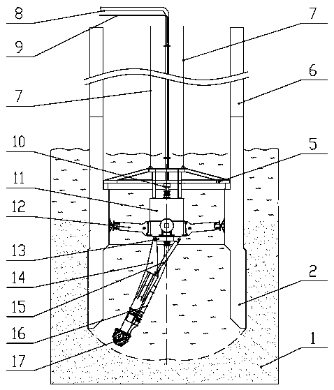
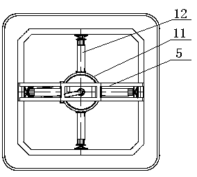
[0027] Example 1, such as Figure 1-2 As shown, an underwater caisson boring machine includes a support seat 5 arranged in the lower part of the shaft 2, the support seat is arranged on a preset cap of the lower part of the caisson, the support seat 5 is connected with a lifting device, and the lifting device is lifted. The device can be a gantry crane or a large floating crane, and 7 pairs of steel wire ropes are used to hoist the supporting seats with double ropes to control the adjustment posture, so that the supporting seats are placed on the preset bearing platform of the lower part of the caisson, and the pump station and the control room are placed on the caisson. department. The upper part of the support base is connected with a steel wire rope, and after the support shoes and the working arm are retracted, the whole set of equipment can be quickly hoisted out through the steel wire rope. The lower part of the support seat 5 is provided with a sealed cabin 11, the sea...

Embodiment 2

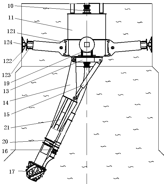
[0029] Example 2, such as image 3 As shown, an underwater caisson boring machine, the driving mechanism includes at least one working arm 14, one or two working arms 14 can be provided, and the number is set according to the excavation diameter. When a working arm 14 is used, the working arm is arranged at the center position of the revolving seat; Telescopic arm 20, telescopic arm 20 is connected with working arm 14 through telescopic oil cylinder 21, and the front end of telescopic arm 20 is provided with twisting suction head 17. The expansion and contraction of the working arm is realized by the telescopic oil cylinder, and the excavation diameter is changed. The compound movement of the above-mentioned mechanism can control the excavation of the rock and soil 1 at the lower part of the caisson with circular and rectangular cross-sections by the twisting suction head.

[0030] Further, one side of the working arm 14 is provided with a telescopic mud pipe 16, and the tel...

Embodiment 3

[0033] Embodiment 3, a construction method of an underwater caisson boring machine, comprising the following steps: S1: Use a tugboat or a large floating crane to place the lower part 2 of the caisson at the design coordinate position, and perform precise positioning of the anchor cable as required. Concrete is injected into the cavity of the lower part of the caisson 2, and under the action of gravity, the lower part of the caisson 2 initially sinks;

[0034] S2: On the working platform above water, the submerged caisson boring machine is hoisted into the lower part 2 of the caisson under the action of the lifting device. The seat 5 is placed on the preset inner wall platform of the lower part of the caisson 2; the power station and the control room are placed on the water working platform, connected to the power pipeline and control pipeline, and connected to the slurry discharge and compressed air pipeline.

[0035] S3: Control the stretcher device 12 to stretch out and tig...


PUM


Abstract

The invention discloses an underwater sinking well heading machine and a construction method thereof, and solves the problems that a sinking well heading machine in the prior art is low in excavationefficiency, not easy to control an excavation contour, and easy to produce deflection of a sinking well gesture. The underwater sinking well heading machine comprises a support seat arranged in a component on the lower part of a vertical well, wherein the support seat is connected with a lifting device; a sealed cabin is arranged on the support seat; a pulp discharge system is arranged on the sealed cabin; a shoe supporting device is connected onto the outer wall of the sealed cabin; a rotating mechanism is arranged on the lower part of the sealed cabin; a heading mechanism is arranged on therotating mechanism; and a lower pulp discharge pipe is arranged on the heading mechanism and is connected with the pulp discharge system. According to the underwater sinking well heading machine andthe construction method thereof provided by the invention, mechanical and controllable excavation is realized, the accuracy of the sinking well gesture is ensured, the underwater operation controllability is high, the excavation efficiency is improved, the problems that a traditional underwater excavation situation is not controllable and the sinking well gesture is hard to control are solved, andthe underwater sinking well heading machine and the construction method thereof have an important significance on high-quality construction operation of an ultralarge-section sinking well with multiple cabin chambers.

Description

technical field [0001] The invention relates to the technical field of underwater tunnel construction, in particular to an underwater caisson boring machine and a construction method thereof. Background technique [0002] The submerged caisson boring machine is a special construction machine, which has the functions of excavating underwater rock and soil, discharging mud-water mixture, excavation contour detection and control, caisson depth and attitude detection, etc., involving geology, civil engineering, machinery, hydraulic, control, measurement and other disciplines. [0003] At present, the piers of large-scale wading bridges are constructed by the multi-caisson method, which has low cost and good quality. However, the conventional simple twister suction mechanism, the position control end is on the well, the distance is long, the flexibility is large, the supporting reaction force is small, the excavation efficiency is low, the excavation contour is not easy to contr...

Claims


Application Information

Patent Timeline
Patent Type & Authority Applications(China)
IPC IPC(8): E02F3/88E02F3/90E02D23/08
CPCE02D23/08E02F3/88E02F3/8808E02F3/907E02D7/28
Inventor 杨聚辉肖威贺飞范磊周倩赵飞付玉龙
Owner CHINA RAILWAY ENGINEERING EQUIPMENT GROUP CO LTD
Why Eureka
Try Eureka