
Constant width beam forming method based on FIR filter

A constant beamwidth and filter technology, applied in the direction of instruments, sounding instruments, etc., can solve the problems of no constant beamwidth, no constant beamwidth, poor robustness, etc.

Inactive Publication Date: 2019-03-19
NANJING UNIV OF INFORMATION SCI & TECH
View PDF5 Cites 3 Cited by
  • Summary
  • Abstract
  • Description
  • Claims
  • Application Information

AI Technical Summary

Problems solved by technology

Among various traditional beamforming algorithms, Capon beamforming, blocking matrix beamforming, etc., do not provide enough constant beamwidth and have low sensitivity to parameter mismatch and poor robustness; while Minimum Variance Distortionless Response (Minimum VarianceDistortionless Response) , MVDR), linearly constrained minimum variance (Linearly Constrained Minimum Variance, LCMV), weighted least squares (Weighted Least Squares, WLS) and other robust beamforming algorithms, although the robustness of the beamforming algorithm has been improved, it still does not have the ideal constant beamwidth

Method used


Image

  • Constant width beam forming method based on FIR filter
  • Constant width beam forming method based on FIR filter
  • Constant width beam forming method based on FIR filter

Examples


Embodiment Construction

[0031] The technical solutions and beneficial effects of the present invention will be described in detail below in conjunction with the accompanying drawings.

[0032] 1. Broadband beamformer structure

[0033] 1.1 Traditional Broadband Beamformer

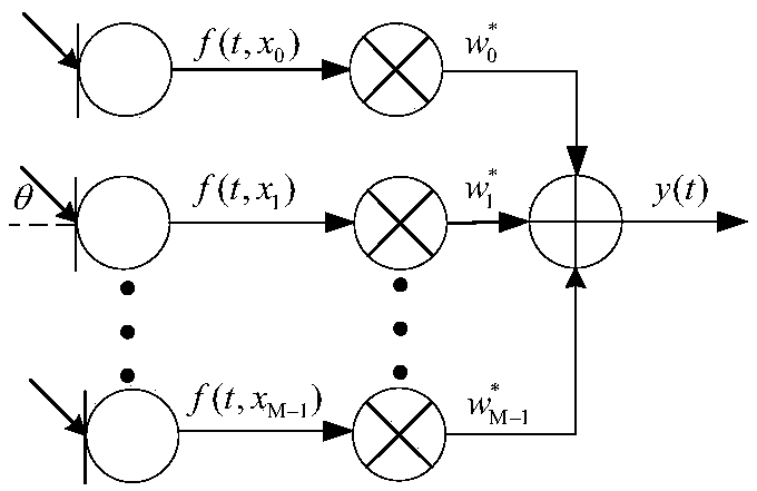
[0034] The classic broadband beamformer structure composed of uniform linear array (Uniform Linear Array, ULA), such as figure 1 shown. In ULA, the microphone position is expressed as

[0035] x m = m d (1)

[0036] In the formula, m represents the microphone index, m=0,1,...,M-1, x m Indicates the array element position corresponding to the mth microphone, d indicates the array element spacing, and M indicates the number of microphone array elements.

[0037] figure 1 Among them, θ is the signal arrival angle (Direction of Arrival, DOA), f(t,x 0 ) means that the microphone position is x 0 , Microphone sampling signal at time t, w m Represents the weighted value of the mth microphone, ()* represents taking the complex ...


PUM


Abstract

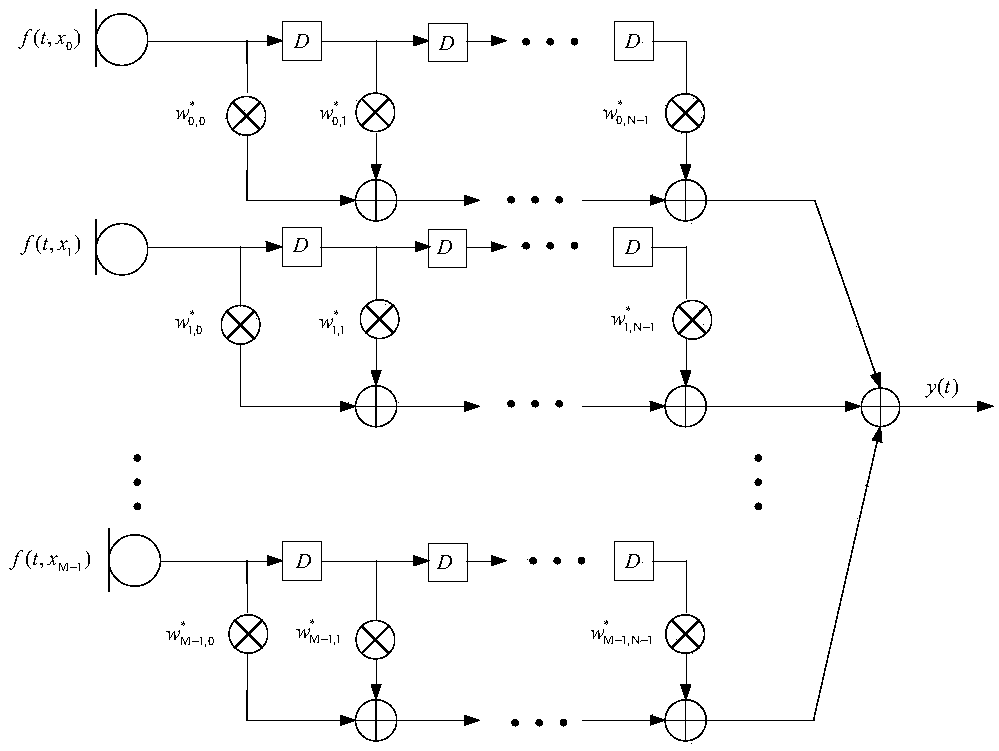
The invention discloses a constant width beam forming method based on an FIR filter, wherein a received signal f (t, x) =[f(t, x0), ..., f(t, xm), ..., f(t, xM-1)] T of a microphone array is processedthrough a beam forming method to obtain an output signal which is shown in the description, wherein f (t, x) represents a sampled signal of the microphone array at a t time position of x, () T represents a matrix transpose, m represents a microphone index, wherein m=0,1,... M-1, M represents the number of microphone array elements, xm represents the array element positions corresponding to the mth microphone, and x=[x0, ... ,xm,... ,xM-1); N represents the order of the FIR filter followed by each microphone, the description represents the coefficient of the n-order FIR filter followed by themth microphone, the superscript * represents the conjugate, and Ts represents the delay between adjacent filters. The method can enable the array to have the same spatial response to input signals with different frequencies within the main lobe width, and the beam forming device with approximately constant beam width and low side lobe array response is designed by utilizing the symmetric properties of the FIR filter array and microphone uniform linear array.

Description

technical field [0001] The invention relates to a constant beam width beamforming method based on FIR filter. Background technique [0002] The amount of information carried by broadband signals in communication systems is more abundant than that of narrowband signals, and processing broadband signals is more conducive to the realization of target detection, parameter estimation and extraction, etc. Since the wideband signal contains different frequency components, if the traditional narrowband beamforming technology is used, the output signal of the array will be distorted, and the wider the signal bandwidth, the more serious the distortion will be. Therefore, applying constant beamwidth beamforming technology to broadband array signal processing to receive signals without distortion as much as possible has become a research hotspot in broadband array signal processing and is widely used in video conferencing, voice processing, and underwater communication. [0003] Consta...

Claims


Application Information

Patent Timeline
Patent Type & Authority Applications(China)
IPC IPC(8): G10K11/34
CPCG10K11/343G10K11/348
Inventor 郭业才陈晨王婷王超
Owner NANJING UNIV OF INFORMATION SCI & TECH
Learn More