

Method for producing mold for use in duplicating light diffusion sheet, light diffusion sheet and method for producing the same, and screen
A light scattering and mold technology, applied in the field of screens, can solve the problems of tool damage, unsatisfactory grinding accuracy, large grinding equipment, etc., and achieve uniform brightness or gain, and good recognizability
- Summary
- Abstract
- Description
- Claims
- Application Information
AI Technical Summary
Problems solved by technology
Method used
Image

Examples
Embodiment 1
[0173] A mold for replicating a light-scattering sheet was produced under the conditions described below.
[0174] (1) Mold matrix material: aluminum sheet (X: 200mm×Y: 100mm)
[0175] (2) Sand blasting conditions
[0176] Sand blasting machine (Model: SGF-4(A); manufactured and sold by Fuji Manufacturing Co., Ltd.)
[0177] Abrasive: aluminum oxide (#180; average particle size: 76μm)
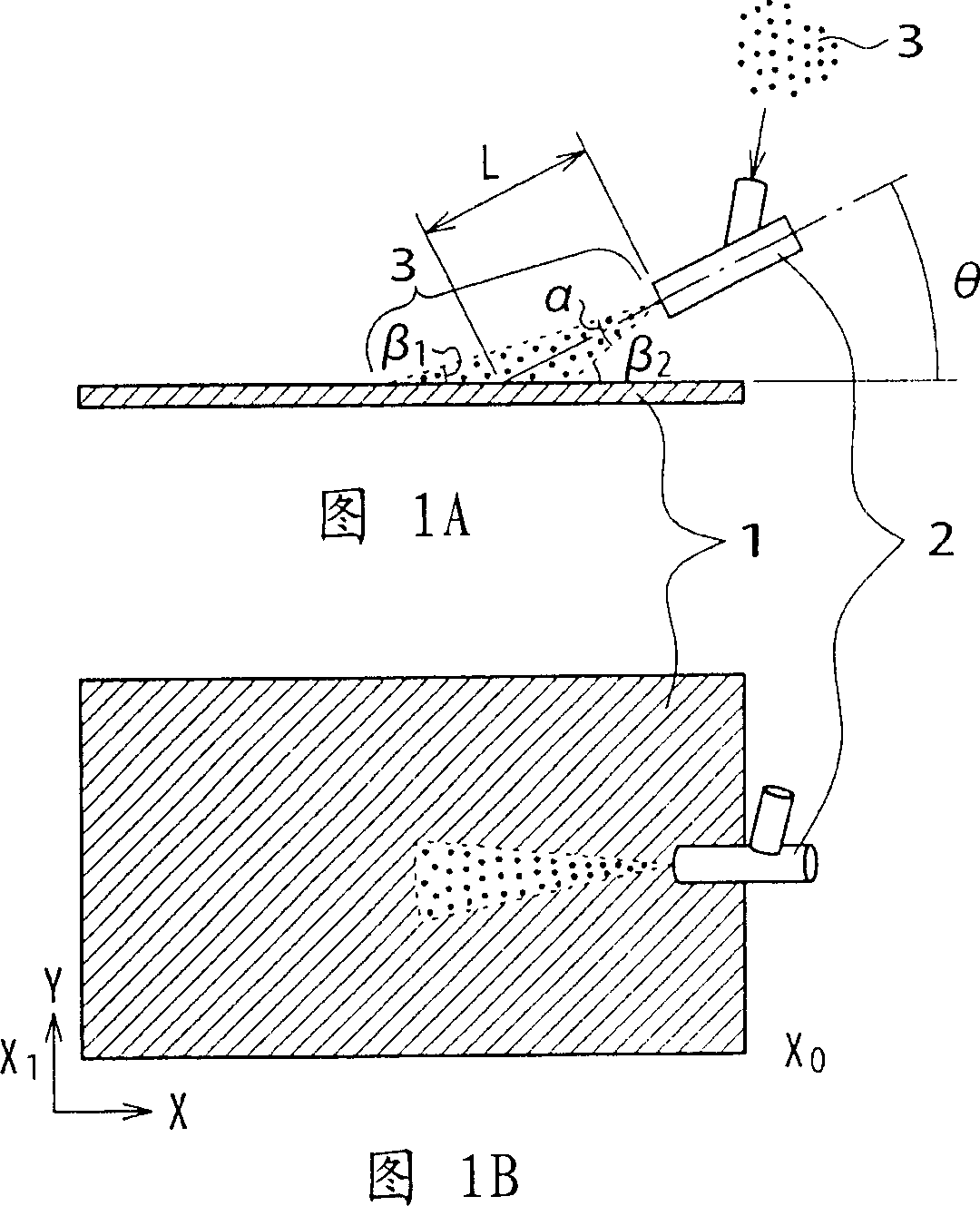
[0178] Distance between spray gun and mold matrix material: 50mm
[0179] Angle between spray gun and mold matrix material: 8°
[0180] Compressed air pressure: 0.5MPa
[0181] Ejection conditions of the abrasive material to the surface of the mold matrix material: Conditions shown in Fig. 1
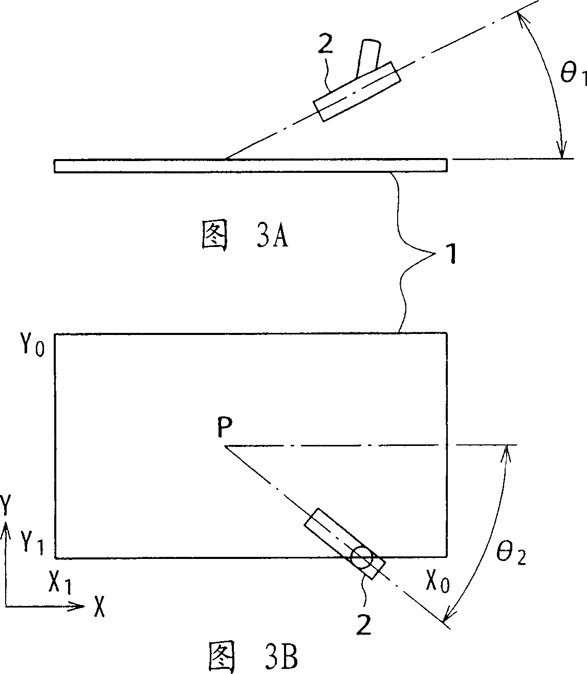
[0182] Spray gun scanning conditions: scan along the X direction at a distance of 5mm and along the Y direction, such as Figure 4 shown.
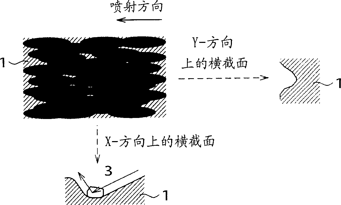
[0183] The surface state of the obtained mold was Figure 7 given in. We saw a state where there was a difference in the surface roughness structure between ...
Embodiment 2
[0186] Next, a transparent resin (PET-G film, DIAFIX; produced and sold by Mitsubishi Plastics, Inc.) was pressed by means of the mold in Example 1 to produce a light-scattering sheet.
[0187] The obtained light-scattering sheet was made to transmit a collimated light beam from the back side of the sheet to measure the scattering angle of the transmitted light emitted from the front side of the sheet. The results are given in Figure 9.
[0188] This light-scattering sheet exhibits such a scattering angle: the scattering angle in the lateral direction (X-axis direction) is different from the scattering angle in the longitudinal direction (Y-axis direction), and the brightness at half-maximum width in the X-axis direction is 18°, and The brightness at half-peak width in the Y-axis direction is 45°.
[0189] In the luminance distribution in the X-axis direction ( FIG. 9( a )), the luminance peak A-axis is shifted by an angle (0°) in the direction perpendicular to the light-scat...
Embodiment 3
[0191] In order to determine the relationship between the angle between the spray gun and the mold matrix material (spray angle) and the anisotropy (axis offset angle) of the scattering characteristics, a sample for replicating a light-scattering sheet was produced under substantially the same conditions as in Example 1. The mold is only gradually changing the angle (spray angle) between the spray gun and the mold matrix material from 2-90°. Then, a plurality of light-scattering sheets were respectively produced using these molds under the same conditions as in Example 2, and each obtained light-scattering sheet was made to transmit a collimated beam from the back of the sheet to measure The brightness distribution of the transmitted light emitted from the side along the X-axis direction.
[0192] From the resulting luminance distribution, the relationship between the spray angle and the anisotropy (axis offset angle) of the scattering characteristics was determined. The resu...
PUM
| Property | Measurement | Unit |
|---|---|---|
| particle size | aaaaa | aaaaa |
| specific surface area | aaaaa | aaaaa |
| thickness | aaaaa | aaaaa |
Abstract
Description
Claims
Application Information