Cyclic cold compress device for orthopedic nursing

A circulating, cold compress technology, applied in the field of medical devices, can solve problems such as compression of the affected area, secondary cracking of the affected area, and patient discomfort, and achieve the effect of installation and disassembly, and easy replacement

Inactive Publication Date: 2019-03-22
李雪芹
View PDF9 Cites 7 Cited by
  • Summary
  • Abstract
  • Description
  • Claims
  • Application Information

AI Technical Summary

Problems solved by technology

[0003] At present, most of the commonly used nursing cold compresses are to apply ice packs directly to the affected area, but the temperature of the ice packs will change with time, which will affect the e

Method used


Image

  • Cyclic cold compress device for orthopedic nursing
  • Cyclic cold compress device for orthopedic nursing
  • Cyclic cold compress device for orthopedic nursing

Examples


Embodiment 1

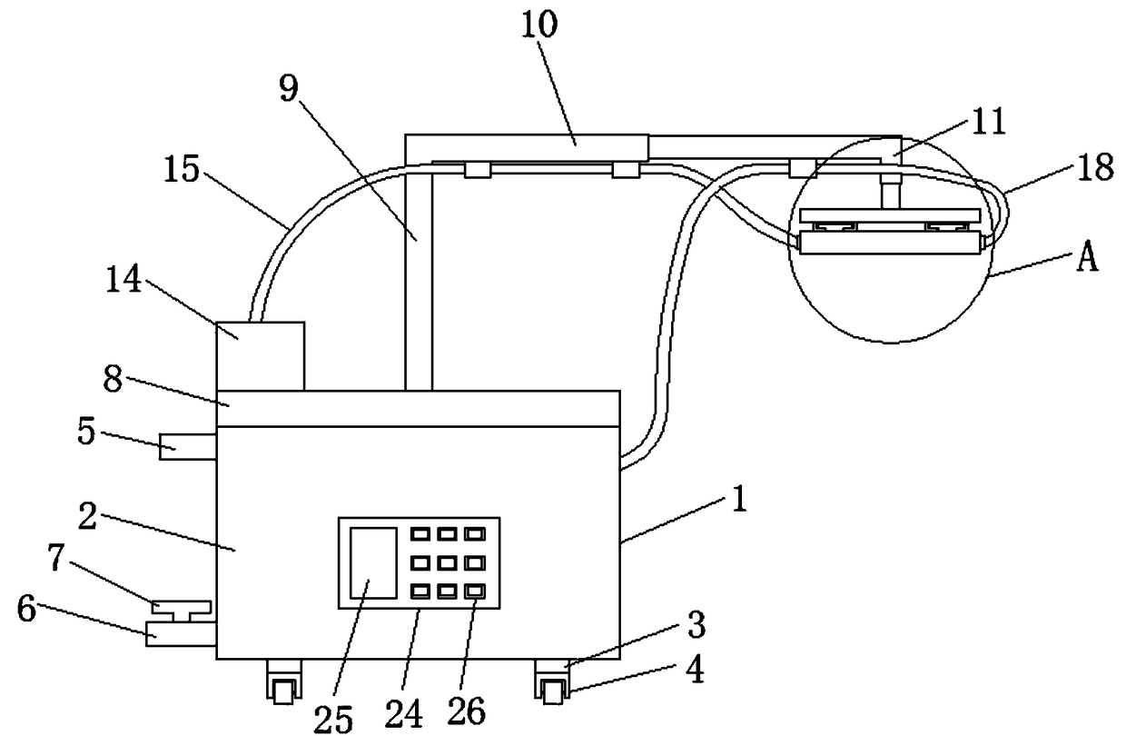
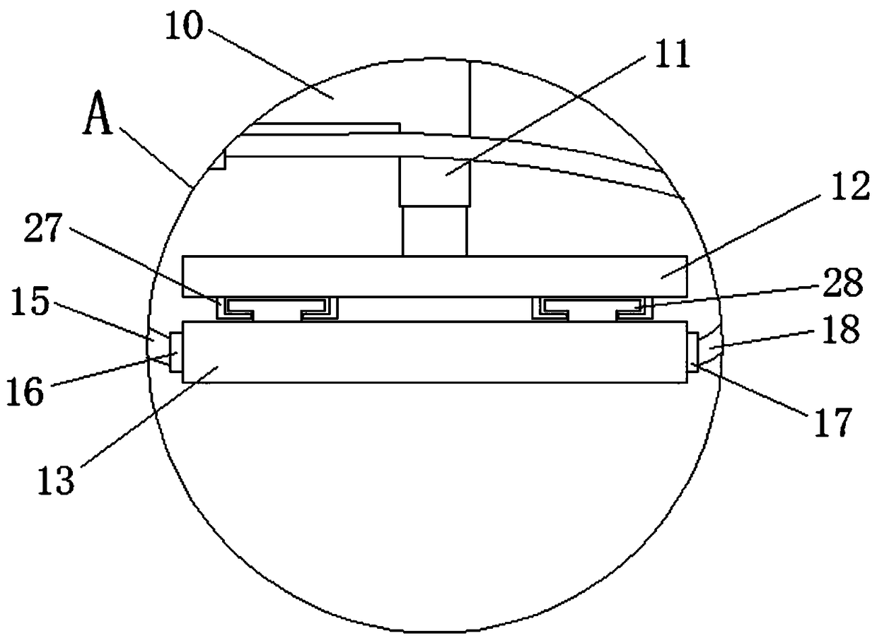
[0026] see Figure 1-3 , a circulating cold compress device for orthopedic care, comprising a device main body 1, the device main body 1 includes a water tank 2, circulating water for cold compress is placed in the water tank 2, and a condenser 8 is fixedly installed above the water tank 2, and the condenser 8 pairs with the water tank The water in 2 is condensed and cooled, and a support device is provided above the condenser 8 to support the cold compress device, preventing the cold compress device from being directly placed on the affected part of the patient, causing oppression, causing discomfort to the patient, and avoiding secondary damage to the affected part. Cracked, a cold compress device is installed on the supporting device, and cold compress nursing is performed on the affected part of the patient.

[0027] The bottom of the water tank 2 is evenly provided with a supporting column 3, which supports the device main body, and casters 4 are installed on the bottom o...

Embodiment 2

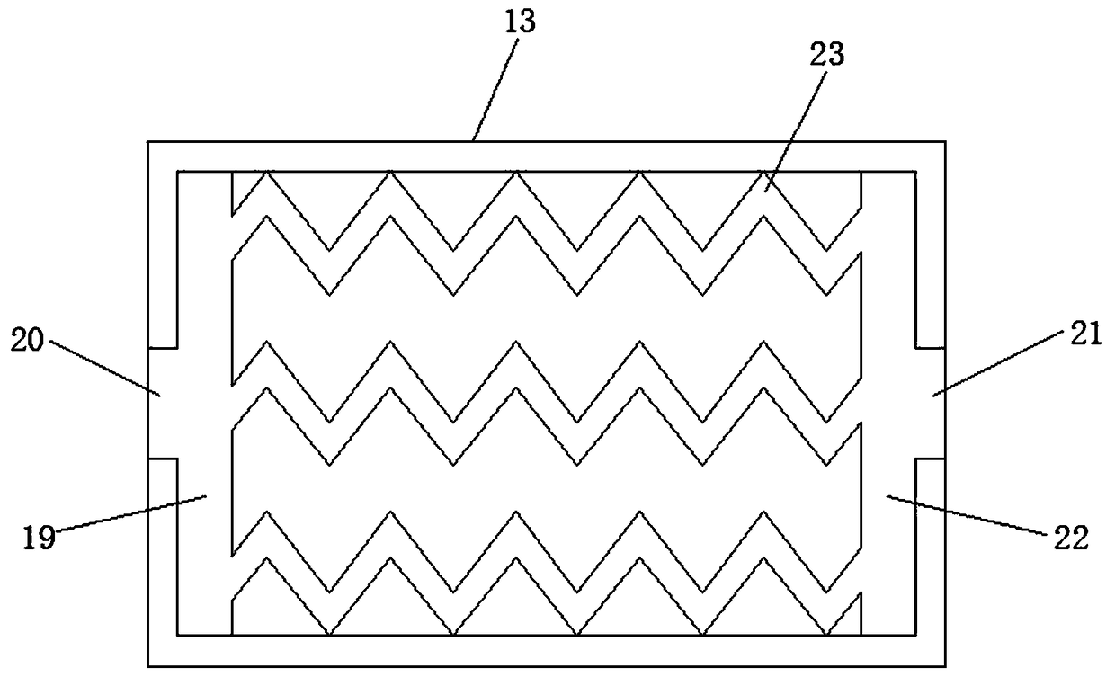
[0036] In order to realize the installation and disassembly of the cold compress belt and facilitate the replacement of the cold compress belt, the following optimization is carried out.

[0037] see Figure 1-3 , a circulating cold compress device for orthopedic care, comprising a device main body 1, the device main body 1 includes a water tank 2, circulating water for cold compress is placed in the water tank 2, and a condenser 8 is fixedly installed above the water tank 2, and the condenser 8 pairs with the water tank The water in 2 is condensed and cooled, and a support device is provided above the condenser 8 to support the cold compress device, preventing the cold compress device from being directly placed on the affected part of the patient, causing oppression, causing discomfort to the patient, and avoiding secondary damage to the affected part. Cracked, a cold compress device is installed on the supporting device, and cold compress care is performed on the affected pa...


PUM


Abstract

The invention discloses a cyclic cold compress device for orthopedic nursing. The cyclic cold compress device comprises a device body which comprises a water tank, a condenser is fixedly mounted abovethe water tank, a supporting device is arranged above the condenser, a cold compress device is mounted on the supporting device, supporting columns are uniformly arranged at the bottom of the water tank, a castor is mounted at the bottom of each supporting column, and a water incoming pipe is connected above the left side of the water tank. By arranging the condenser above the water tank, a coldcompress belt is connected with the water tank through a cold compress belt water incoming pipe and a cold compress belt water outgoing pipe, and a first water distribution pipe, an elbow and a secondwater distribution pipe are arranged in the cold compress belt to realize circulating to enable ice water to exist in the cold compress belt continuously, so that impact on cold compress effect due to temperature rise of water in the cold compress belt is avoided; by arranging the supporting device in the middle above the condenser to support the cold compress device, discomfort of a patient caused by the fact that the cold compress device is directly put at an affected part of the patient, thereby compressing the affected part is prevented.

Description

technical field [0001] The invention relates to the technical field of medical devices, in particular to a circulating cold compress device for orthopedic care. Background technique [0002] Orthopedic patients often experience swelling and pain in the affected area before and after surgery, and cold compresses are needed to reduce the swelling. Applying ice packs or cold wet towels to the lesion can promote local vasoconstriction, control bleeding of small blood vessels and reduce tension The pain of the lump can achieve the effect of reducing swelling and relieving pain, reducing local blood flow, preventing the spread of inflammation and suppuration, and playing an important role in the care of patients with the affected area. [0003] At present, most of the commonly used nursing cold compresses are directly applying ice packs to the affected area, but the temperature of the ice packs will change with time, which will affect the effect of cold compresses, and the pressur...

Claims


Application Information

Patent Timeline
IPC IPC(8): A61F7/00
CPCA61F7/00A61F2007/0056
Inventor 李雪芹董娜张华钰刘艳萍刘丽
Owner 李雪芹
Why Eureka
Try Eureka