Steel bar bending machine

A steel bar bending and steel bar technology, which is applied in the field of transmission line construction equipment, can solve the problems of galvanized layer wear and labor intensity, etc., and achieve the effect of reducing the probability of wear, reducing labor intensity, and convenient operation

Pending Publication Date: 2019-03-22
STATE GRID CORP OF CHINA +2
View PDF0 Cites 4 Cited by
  • Summary
  • Abstract
  • Description
  • Claims
  • Application Information

AI Technical Summary

Problems solved by technology

[0003] The purpose of the present invention is to provide a steel bar bending machine, aiming to solve the technical problem that the galvanized layer on the surface of the grounding down conductor is easily worn out by using a steel bar wrench for bending, and the labor intensity is high

Method used


Image

  • Steel bar bending machine
  • Steel bar bending machine

Examples


Embodiment Construction

[0019] In order to make the technical problems, technical solutions and beneficial effects to be solved by the present invention clearer, the present invention will be further described in detail below with reference to the accompanying drawings and embodiments. It should be understood that the specific embodiments described herein are only used to explain the present invention, but not to limit the present invention.

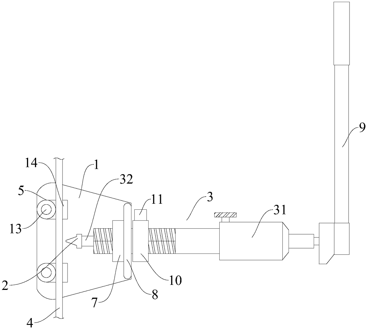
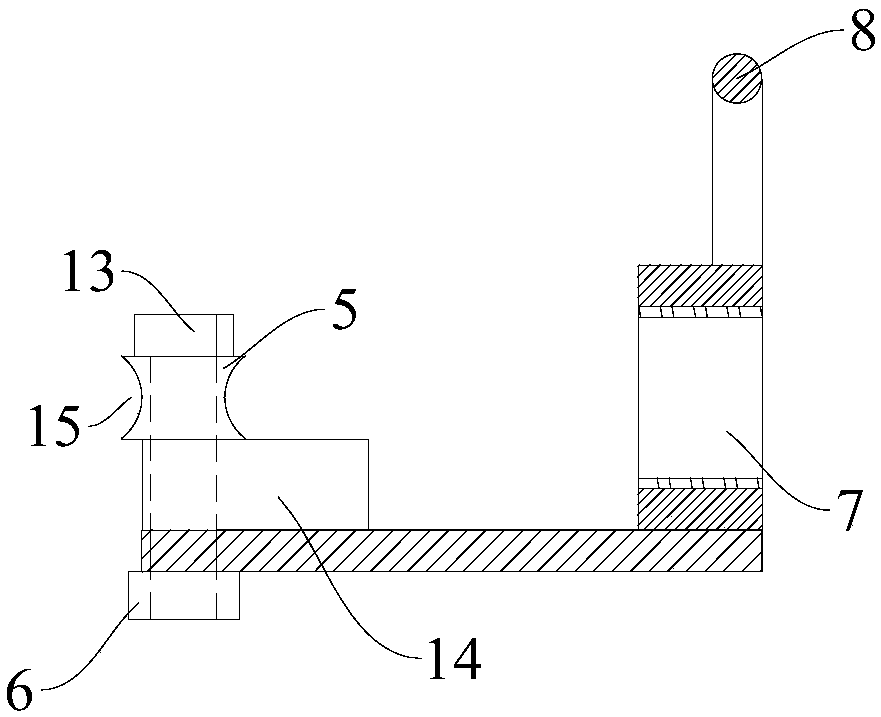
[0020] Please also refer to figure 1 and figure 2 , the steel bar bending machine provided by the embodiment of the present invention will now be described. The steel bar bending machine includes a base 1 and a pressure head 2 arranged above the base 1. The pressure head 2 is connected with the movable end of the hydraulic device 3 arranged on the base 1. The base 1 is also provided with a rotating connection with the base 1 and There are two rotating rollers 5 for abutting against the steel bar 4 , and the rotating rollers 5 are respectively arranged on bot...


PUM


Abstract

The invention provides a steel bar bending machine, and belongs to the technical field of power transmission line construction equipment. The steel bar bending machine comprises a base and a pressurehead arranged above the base; the pressure head is connected with the movable end of a hydraulic device arranged on the base, and two rotating rollers rotationally connected with the base and used forabutting against steel bars are further arranged on the base, and arranged on the two sides of the pressure head correspondingly; vertical columns are arranged on the base, and the rotating rollers rotationally sleeve the vertical columns; cushion blocks sleeving the vertical columns and used for supporting the rotating rollers are arranged below the rotating rollers; and bolts are adopted as thevertical columns and penetrate through the base to be in threaded connection with nuts arranged at the bottom of the base. According to the steel bar bending machine provided by the invention, the technical problems that a steel bar wrench is adopted to bend, abrasion of a zinc coating of the surface of a grounding down lead is prone to being caused, and the labor intensity is large are solved.

Description

technical field [0001] The invention belongs to the technical field of transmission line construction equipment, and more particularly relates to a steel bar bending machine. Background technique [0002] Nowadays, the construction technology standards of transmission lines are gradually improved, and the installation of grounding down conductors is one of the important standard processes. However, due to the different dimensions of different foundations, the grounding down-conductor cannot be prefabricated and bent in the factory, and can only be bent on site to fit on the corresponding foundation. At present, the grounding down-conductor is generally simmered and bent with a self-made steel wrench, which is very easy to cause wear of the galvanized layer on the surface of the grounding down-conductor and is labor-intensive. SUMMARY OF THE INVENTION [0003] The purpose of the present invention is to provide a steel bar bending machine, which aims to solve the technical ...

Claims


Application Information

Patent Timeline
Patent Type & Authority Applications(China)
IPC IPC(8): B21F1/00
CPCB21F1/004
Inventor 刁昌盛杜天杰窦旭裴海山
Owner STATE GRID CORP OF CHINA
Why Eureka
Try Eureka